Torque measurement system
Torque measurement system is intended for periodical control and endurance testing of various moving structural elements, e.g. turbine blades, etc.

Torque measurement system is intended for periodical control and endurance testing of various moving structural elements, e.g. turbine blades, etc.
of the torque measurement system
of torque measurement system
Depending on the particular task to be solved, there are two available configurations of the torque measurement system:
Torque measurement system
The sensing element of the torque measurement system is represented by a strain-gauge bridge used for the control of shaft deformation. Depending on the particular task, the torque measurement is performed by means of measurement module ZET 7110 (statical measurements) or ZET 7111 (dynamic measurements). A detailed manual on the connection of strain gauges to ZETSENSOR modules is available in the Clause “Establishing strain-gauge bridges“.
In the case of static measurements, data transfer to PC is performed by interface converter ZET 7174.
In the case of dynamic measurements, the data received from measuring module ZET 7111 is saved to the offline recorder ZET 7173 (the recorder is mounted on the rotor shaft together with the batteries used for power supply of the recorder).
Interface converter ZET 7174 is used for configuration of the instruments included into the scope of the measuring system.
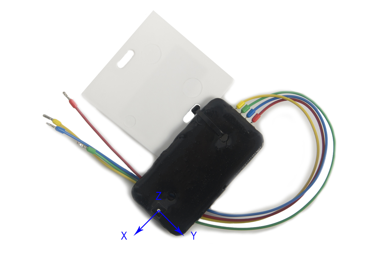
Digital accelerometers ZET 7152-N or ZET 7152-E (laboratory version, plastic casing) are used for the vibration level control of the rotor shaft.
It is also possible to transfer the data by radio channel. Telemetering system ZET 7172 is used for wireless data transfer from the measuring network to the PC via interface converters ZET 7174 or ZET 7176 for further data processing. Module ZET 7172-S included into the scope of the telemetering system, has an integrated linear acceleration sensor ZET 7152-N, which allows to determine rotation frequency value without implementing any additional measuring instruments.
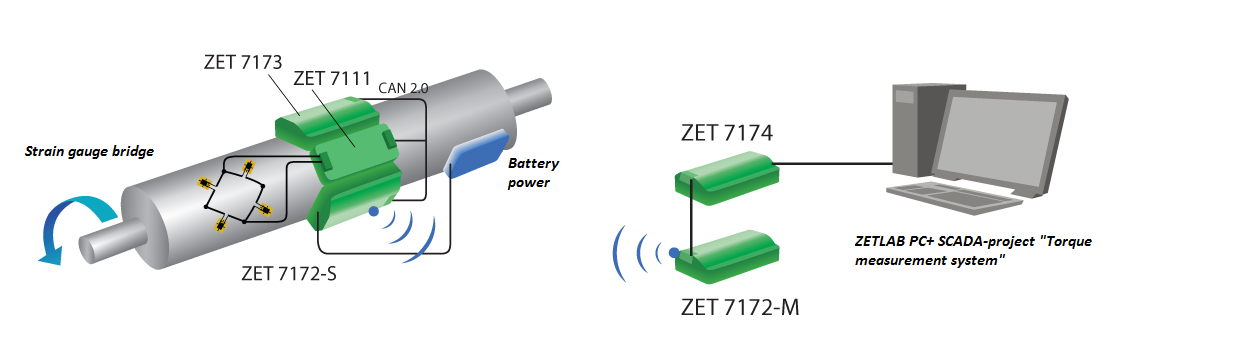
Module ZET 7172-S is mounted on the rotating element in such a way so that Z axis of the integrated sensor ZET 7152-N would be transverse to the rotation axis, and Y axis would be aligned with the shaft curve.
The system is scalable and perfectly suits for the measurement performance in the case if the measurement points are located far from each other.
For the purpose of measurements performance, there is used a program included into the scope of SCADA ZETVIEW.


Torque measurement with the use of ZETSENSOR module
System deployment for shaft torque measurement
The torque measurement system can be implemented as an independent system or be a constituent part of the measurement system based on the digital modules of ZETSENSOR series.

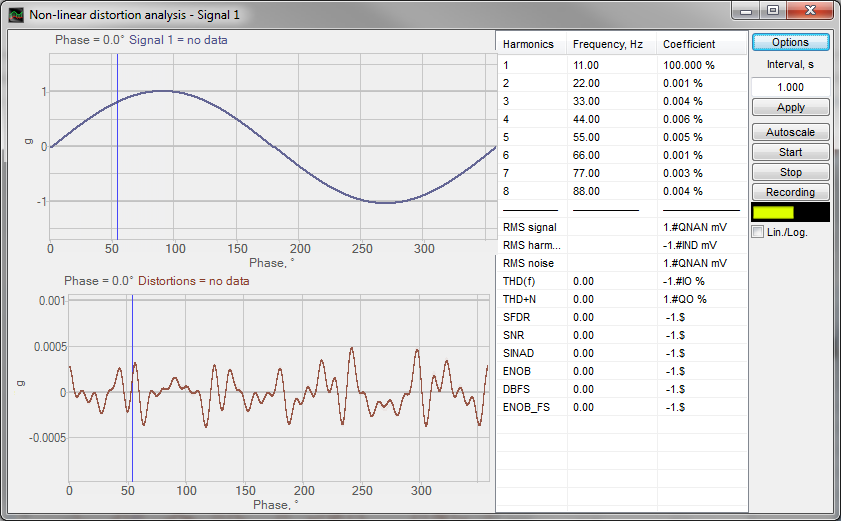
Torque measurement system can also be used for the control of rotary oscillations attributed to changes in the dynamics of torque value in time domain and to the fluctuations in the resistance level. In this case, it is necessary to use two standard units of the system, which should be mounted at the opposite sections of the shaft. The program “Non-linear distortions analysis” from the scope of ZETLAB ANALIZ is used for torsional oscillation frequency measurements.
In the course of torsiography and engine shaft torsional oscillations measurements, the parameters of torsional oscillations are calculated based on tilt angle and shaft rotation frequency. Due to this, it is necessary to register the shaft tilt angle in relation to the top dead center (hereinafter referred to as TDC).
In order to solve this task, there is used digital accelerometer ZET 7152-N, which is included into the scope of the dynamic testing system based on modules of ZETSENSOR series. The transducer can be mounted directly on the shaft or at some distance (R) from the shaft rotation axis. As a rule, at the rotating elements of electrical motors there is placed a special label, which corresponds to the TDC. The accuracy of measurements depends on the position of accelerometer’s sensing element in relation to the zero label of shaft position.
The calculations will be conducted based on zero position at Y axis, the direction of sensing elements axes should be as follows:
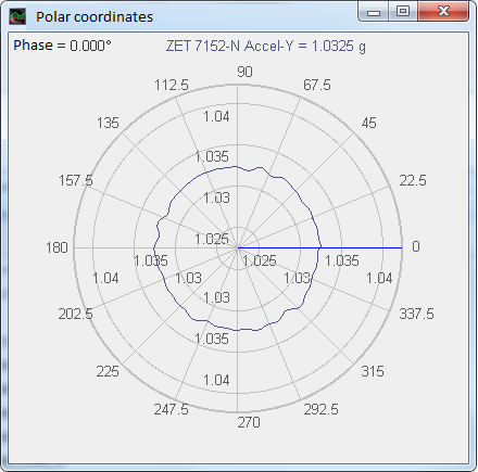
This type of transducer positioning allows to control several important parameters:
Hence, the R distance should be selected in such a way, so that the radial acceleration ac would not exceed the value of 8 g for accelerometer ZET 7152-N (∼400 g for accelerometer при использовании ZET 7152-E respectively).
For instance, for rotation velocity of 300 RPM the distance should not exceed 40 mm.
Torque measurement system
The sensing element of the torque measurement system is represented by a torque sensor. For the purpose of particular specimen testing there is used a special platform with mounting fixture for the torque sensor and the tested specimen. In the course of measurements performance, the torque sensor should be firmly attached to the platform and the rotating specimen.


The torque sensor is connected to the strain-gauge station ZET 017-T8. ZETLAB TENZO Software delivered together with the strain-gauge station enables all types of measurements, including torsiography.
Integrated strain-gauge station generator provides the power supply for the sensor. It is possible to configure the corresponding parameters in the “Signal generator” program.
In order to measure the torque with a strain-gauge sensor and a strain-gauge sensor, there is used a program “Strain-gauge meter“. It is necessary to specify the required sensitivity level and the measurement limits in the program settings. The torque value is depicted in the corresponding indicator of the program.
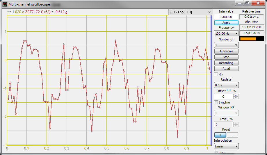
“Multichannel oscilloscope” program allows to create a graph of torque characteristics dynamics. It is possible to select a signal to be displayed from the signals, created by the program “Strain-gauge meter“.
For the purpose of complete measurement performance, there is used a control unit, which establishes connection between the output of the tested unit and the strain gauge station, as well as provides supply of test signals from the strain gauge module to the tested unit. The scope of automated test system also includes programmable power supply source.

The tests are performed in automated mode by means of task-specific software “Torque measurement system” implemented in SCADA ZETVIEW. An example of program operation is shown in the figure below. Upon tests completion, there is produced a report with measurements results, graphs, and characteristics of the tested specimen.

of torque measurement system
complex tests in automated mode
of the measurement system depending on the task to be solved
the system incorporates certified components
stable characteristics throughout operational life
the measuring instruments and the WKS cab be located at considerable distance from each other
are produced automatically in accordance with the selected template
* Torque measurement system based on the transducers of ZETSENSOR series
For the purpose of test system verification and calibration of the torque sensors, there is used a special torque measurement instrument placed on the mounting fixture and having two branches. The measurements are performed by means of strain-gauge station ZET 017-T8 and task-specific software ZETLAB TENZO. The “Strain-gauge meter” program is used for torque measurement.


The weights with certain mass are sequentially attached to one of the two branches at a certain distance, which leads to the change of the torque value. For instance, when a 100 gr weight is attached to the branch at the distance of 100 mm, the torque value will be 0,1 Nm, for the weight 50 gr the value will be 0,05 Nm, for 200gr – 0,2 Nm.
of the torque measurement system
Measuring system based on the transducers of ZETSENSOR series (offline automated tests) POR (price on request)
Measurement system based on transducers of ZETSENSOR series (dynamic measurements in real-time mode) POR (price on request)
Measuring system based on a strain-gauge station POR (price on request)
Torque measurement system can also be used as a torsiograph for detection of critical load. It is necessary to consider specimen parameters when choosing the measuring instrument:
Please note that the personal data provided by you is used exclusively for the purposes of fulfilling our contractual obligations, including, but not limited to: issuing invoices, delivery documents, documentation relating to customs clearance process, etc. We do not provide your personal data to any third party except for the purposes relating to our direct contractual obligations. Upon completion of order processing and expiry of the warranty period for the Products provided by our Company, we do not store or process any of your personal data. Please note, that our Company’s Confidential policy does not imply any advertising or marketing activities with the use of your personal data (including your Company name, address, your E-mail, phone number and other information provided by you with a view to placing an Order and organization of the Delivery).