ZET 7110-DS digital small strain gauge


- Tensile and compression testing
- CAN 2.0 interface
- Self-monitoring
POR (price on request)
* Minimum order value: from 7 700 USD
Specifications
of ZET 7110-DS digital small strain gauge
| Metrological specifications | |
|---|---|
| Measured parameter | deformation, micro-strain |
| Sensor type | integrated sensing element |
| Measured range | 0…1600 µm/m |
| Measurement range without the use of mounting panel | 0…300 µm/m |
| Measurement range with the use of mounting panels (in different mounting points) | 0…600 µm/m 0…1100 µm/m 0…1600 µm/m |
| Sensitivity threshold depending on the range, µm/m: from 0 to 300 from 0 to 600; from 0 to 1100; from 0 to 1600. |
2 µm/m 4 µm/m 8 µm/m 12 µm/m |
| Temperature impact on sensitivity, 10 °C (from the measuring range) | 2 % |
| 24 hours zero drift | 0,5 % |
| Restoring force | 1500 N |
| Failure strain (without the use of mounting panels) | 500 µm/m |
| Operability control in real time mode | sensor temperature synchronization quality data quality |
| Measurement reliability check | sensing element integrity check measuring circuit range |
| Technical specifications | |
| Data interface | CAN 2.0 |
| Exchange speed | 100, 300, 1000 kbps |
| Data output frequency | 1 Hz |
| Operational specifications | |
| Dimensions | 197×56×30 mm |
| Weight | 300 g |
| Device power | from 9 to 24 V |
| Consumed power | 0,5 W |
| Polarity reversal protection | yes |
| Operational temperature range | from -40 to +100 °C |
| Available product versions | Standard (protection class IP65) Explosion-proof* (explosion protection class 0ExiaIICT6 X (IP67)) |
| Electromagnetic compatibility EMC | |
| IEC 61000-4-2, ESD | contact 8 kV, air 15 kV |
| IEC 61000-4-4, EFT | power 4 kV, signal 2 kV |
| IEC 61000-4-5, Surge | 4000 V |
* The price is calculated on individual basis
Function
of ZET 7110-DS digital small strain gauge
ZET 7110-DS digital small strain gauge (with integrated strain gauge) is also used for stress-strain state control of concrete structures, it is used within the scope of engineering structures monitoring systems (both stationary and mobile).
Digital small strain gauge is used for stress-strain state control and alarm notification in the case of elastic range of stress value exceeding. ZET 7110-DS digital small strain gauge is supplied in air-tight shock-proof package with dust and moisture protection.
ZET 7110 DS digital strain-gage transducer allow to conduct indirect measurements, related to deformation control (bending, torque, force). It should be noted, that in this case, the sensitivity of the transducer is evaluated by means of the on-site calibration. The adjustment ratio is set in the “Formula” program available in ZETLAB Software.
Advantages
of ZET 7110-DS digital small strain gauge
Measurement results
are displayed in digital format
No adjustment required
all characteristics are stored in the measuring module memory
Integrated PT
the calculations are performed in close vicinity to the primary transducer
User-friendly design
easy installation and measurements performance
Reliability
stable operational charactericstics


Operating principles
of ZET 7110-DS digital small strain gauge
ZET 7110-DS digital small strain gauge consists of a primary transducer and ZET 7110 measuring module.
Each digital small strain gauge can be configured individually depending on particular requirements. Configuration is saved in ZET 7110 measuring module memory. Thus, using digital strain gauges allows to start measurements immediately without configuring any parameters – the results are displayed in the set measuring values (kg, N, Pa, mm, etc.).
ZET 7110-DS digital small strain gauges have two FQ14-4ZK-S 4-contact connectors for connection to measuring network (mating connector is included into delivery scope).
The sensors are fixed on the controlled object while the interface units ensuring information transmission are placed inside of electrical cabinet.
ZETSENSOR elecrical cabinet is more compact than available analog versions. ZETSENSOR digital modules are easy to install and de-install, they also have power supply and data transfer digital indication, which simplifies in-place diagnostics of the system.


| Contact # | Designation |
|---|---|
| 1 | +(9…24) V |
| 2 | CAN 2.0 line “H” |
| 3 | CAN 2.0 line “L” |
| 4 | GND |
Mounting
of ZET 7110-DS digital small strain gauge
In order to evaluate deformation level of the controlled object, it is necessary to make sure that the sensor mounting axis is aligned with the controlled deformation direction during mounting of the sensor.
The sensor is mounted on the controlled object via two points and a slot, which allows to mount the sensor at a distance of 180±5 mm.
The transducer is mounted on the structural elements exposed to the tensile load at the areas, that are exposed to the minimal possible load. In addition to proper mounting technique of the transducer, it is also necessary to provide minimal preliminary strain of the sensitive surface. To do that, after havng fixed the first connection point of the transducer, apply the load of 10-30N (1… 3 kg) to the second connection point of the transducer prior to fixing it.
For sensors mounting on a concrete surface tie bolts and anchor connections with M8 thread are used.
Mounting on steel surface should be performed by means of weld stud M8 or M8 mounting bolts.
In the course of ZET 7110-DS digital small strain gauge mounting, it is necessary to provide reliable fixation at the mounting points in order to prevent slipping or displacement. To ensure reliable fixation, it is recommended to use DIN 6798 A stainless serrated washer “M8”.
Relative deformation measurements range depends on the particular mounting technique used.
In the case of deformation measurements within limit of 300 µm/m, the connection points of the transducer are exposed to the load up to 1500 N (150 kg), thus, it is necessary to secure sufficient bolt tightening force, so that to prevent slipping at the mounting points.
The transducer is intended for tensile deformation measurements, thus, the presence of bending and twisting deformations will result in minor inaccuracy of measurement results.


Temperature fluctuations: impact on measurement results
of ZET 7110-DS digital small strain gauge
For measurements in the range of 20 °C, the gauge readings error is within 10 µm/m. Below you can see an example – measurements of Digital small strain gauge sensor ZET 7110-DS mounted on a steel U-section.


Practical application
of ZET 7110-DS digital small strain gauge

Small strain gauge sensor ZET 7110-DS is used within the stress-strain state control and displacement moninoring systems included into Structural health monitoring system.


Measuring network diagram
based on ZET 7110-DS digital small strain gauge
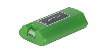
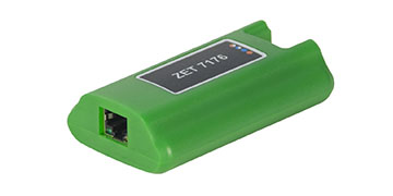
For establishing of the measuring network, ZET 7110-DS digital small strain gauges are connected sequentially. The resulting measuring chain is connected to PC via interface converters ZET 7174 (CAN ↔ USB), ZET 7176 (CAN ↔ Ethernet or Wi-Fi), ZET 7177 (CAN ↔ GSM).

Specialized calculator
for calculating the required type of cables in the construction of measuring lines
For visual representation of the measured values one can use such programs as “DC Voltmeter”, “Multi-channel recorder” and other programs included into the scope of ZETLAB SENSOR Software (supplied together with interface modules). In the case if visual representation of a large amount of measuring channels is necessary, one can use Multichannel measurement system program. Depending on program settings, the measurement results can be represented as force, weight, displacement, torque and other parameters.
Control
of ZET 7110-DS digital small strain gauge
All necessary settings are saved in ZET 7110-DS measuring module memory. In the case if it is necessary to change the settings of the digital sensor (for instance, during periodical verification), one should connect the module to PC via interface converter and start “Device manager” program.
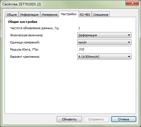
Measuring module configuration
«Settings» tab
Measuring channel settings
| Parameter | Adjustable? | Acceptable values | Description |
|---|---|---|---|
| Data refresh rate, Hz | Yes | 1 5 25 125 |
Sampling frequency (for ZET 7110-DS digital small strain gauge) |
| Physical value | Yes | Deformation Strain |
“Deformation” value is selected in the case if it is necessary to control relative deformation. “Strain” value is selected when it is necessary to measure strain value (and the material elasticity module is known) |
| Measuring unit | Yes | µm/m mm/m cm/m m/m % Pa kPa MPa |
The values are used for identification of measurements physical units Measuring units − «µm/m», «mm/m», «cm/m», «m/m», «%» relate to the parameter «Physical value» − «Deformation». Measuring units − «Pa», «kPa», «MPa» relate to the parameter «Physical value» − «Strain» |
| Young’s modulus
(modulus of elasticity) hPa |
Yes | – | Young’s modulus (modulus of elasticity) is a physical value characterizing material resistance to deformation. This parameter can be selected if «Physical value» − «Strain» option is chosen. |
| Mounting option | Yes | A (±300 µm/m) B (±450 µm/m) C (±600 µm/m) D (±1800 µm/m) |
Gauge measuring range depends on particular mounting option implemented. |
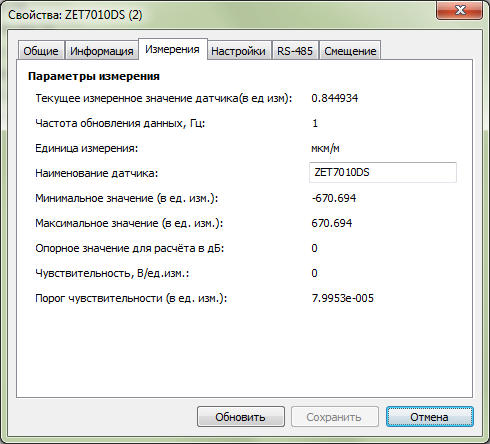
"Measurements" tab
“Measurements” tab contains measuring channel information. This tab allows to set measuring channel name.
"Offset" tab
“Offset” tab allows to set gauge readings offset value.
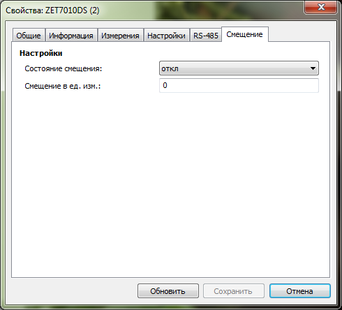
| Parameter | Adjustable? | Accepted values | Description |
|---|---|---|---|
| Offset state | Yes | off on |
Activation / deactivation of resetting the measured data to the value specified in “Offset units” parameter |
| Offset values | Yes | – | Allows to assign a value to be set as the current one for the digital sensor. All further readings changes will be processed in accordance with the value set. |
Digital sensors:
examples of “Offset” function use
Example #1
It is know that the structure element has been exposed to a pre-strain impact in the amount of 500 mPa prior to sensor mounting. In order to take the pre-stressed state into consideration, set “500” in the “Offset values” Section and “On” in the “Offset state” Section, then click “Save” key. The digital sensor will then start recording the controlled object stress-strain state based on pre-stressed value of 500 mPa.
Example #2
Upon completion of strain gauge sensors mounting, the controlled object is placed into position, starting from which it is necessary to start deformation control measurements. Set “0” into “Offset value” Section and “Off” in the “Offset state” Section, then click “Save” key. The digital sensor will start recording the controlled object stress-strain state from the set “zero” position.
Parameters configuration: general information
ZET 7×10 DS digital small strain gauge has an integrated resistive-strain sensor with bridge-connection mounting.
ZET 7×10 DS digital small strain gauge configuration procedure:
— Relative deformation measurements: set the following parameters in “Settings” tab:
— Physical value – “Deformation”;
— Measuring units– set the required measuring values («µm/m», «mm/m», «cm/m», «m/m», «%»);
— Mounting option – select mounting option of ZET7x10 DS digital sensor («A (±300 µm/m)», «B (±450 µm/m)», «C (±600 µm/m)», «D (±1800 µm/m)»).
— Material strain measurements: set the following parameters in “Settings” tab:
— Physical value – “Strain”;
— Measuring units– set the required measuring values («Pa», «kPa», «mPa»).
— Young’s modulus, hPa – set the controlled structure element elasticity modulus (elasticity modulus values of some of the materials are specified in the Table below);
— Mounting option – allows to select ZET7x10 DS digital sensor mounting option («A (±300 µm/m)», «B (±450 µm/m)», «C (±600µm/m)», «D (±1800 µm/m)»).
| Material | Modulus of elasticity value (E) (hPa) |
|---|---|
| Aluminium | 69 |
| Copper | 100 |
| Steel | 210 |
| Glass | 60 |
| Concrete | 20 |
Download
user manual for operation of the digital transducers
Metrological self-monitoring
of ZET 7110-DS digital small strain gauge
Small strain gauge sensor ZET 7110-DS has metrological diagnostic self-monitoring function — in particular, auto-check of sensor serviceability while being in operation. Based on positive results of metrological self-monitoring, it is possible to increase inter-verification interval without implementing standard verification procedure.
There has been developed a special software for metrological self-monitoring of ZETSENSOR digital transducers in automatic mode.
Main window of “Metrological self-monitoring ZET 7XXX” software is shown in the figure. The “Metrological self-monitoring” tab allows the user to select the type of device, test type, measurements control and to receive the self-check results.

Test impact types
AC - alternating signal
FR: «Required frequency value»: «Frequency tolerance» – alternating signal frequency;
AM: «Required signal amplitude value»: «Signal amplitude tolerance» – alternating signal amplitude;
OF: «Generated signal bias»: «Generated signal bias tolerance» – generated signal bias;
TM: «Signal analysis time» – signal control time (minimal signal analysis time for transient processes or long-time tests)
Example:
AC;FR:0.5:0.01;AM:0.4:0.002;OF:0.1:0.0001;TM:5 –
Alternating signal with frequency: 0.5 ± 0.01 Hz, amplitude: 0.4 ± 0.002 V, bias: 0.1 ± 0.0001 V, minimal signal control time – 5 s.
DC - constant signal
LE: «Required signal level»: «Signal level tolerance» – generated signal level.
TM: «Signal analysis time» – control signal time (signal analysis minimal time for transient and long-time processes tests)
Example:
DC;LE:0.5:0.001;TM:5 –
constant signal: 0.5 ± 0.001 V, minimal signal control time – 5 s.
ST1 - stepwise change
AM: «Minimal value»: «Maximum value» – change range.
TM: «Signal setting time» – time before signal control start
Example:
ST1;AM:100:200;TM:5 –
stepwise change: for 100..200 units, minimal signal control time – 5 s.
ST2 - stepwise change
MD: «Minimal change»: «Maximum change» – change amplitude.
TM: «Signal setting time» – time before signal control start
Example:
ST2;MD:10:10.5;TM:6 –
stepwise change: for 10..10.5 units in modulus, minimal signal control time – 6 s.
PPS - Pulse-per-second signal
SP: «Acceptable counts deviation» – amount of counts before or after start of a second.
Level change to be checked one time in a second.
Example:
PPS;SP:2 –
the change should take place in the beginning of a second, 2 counts.
Device type is selected from the dropdown list. To select the device type, you have to left-click the element, and to select the required device to be checked from the pop-up list.
Selector is used to choose the test. To change test number you have to left-click the number and to set the required value with the scroll wheel. If self-check is run, selector remains inactive till the moment the user stops the project operation or till the self-check is finished.
There is a button to activate and stop the measurements. During diagnostics the button is green, and grey when the diagnostics process is suspended.
Indicator serves as a timer showing how much time is left before the current test is finished. It takes the count after any test is begun. Test results are shown in the log.