
Harmonic Distortion Analysis
The software is used for automatic measurement of the harmonic distortion factor and voltage r.m.s. of signals coming to the input channels of FFT spectrum analyzers. Adjustment to the frequency of the main component is performed automatically. The program is based on the measurement of the voltage r.m.s. of higher components by an external or internal reference signal.
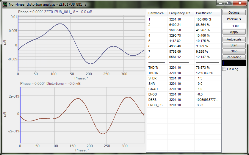
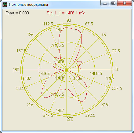
In the program window Harmonic distortion analysis, the signal diagram and its corresponding form of harmonic distortions as well as the main component frequency values and measured harmonic distortion factor are displayed in % or decibels (dB). It is also possible to display the harmonic distortion form in polar coordinates. The harmonic distortion form allows to estimate the real signal deviation from the theoretic sine curve.
Harmonic distortion analysis presents the results as the following characteristics:
- THD — Total Harmonic Distortion.
- THD+N — Total Harmonic Distortion with Noise.
- SNR — Signal-to-Noise Ratio.
- SFDR — Spurious-Free Dynamic Range.
- SINAD — Signal-to-Noise and Distortion ratio.
- ENOB — Effective Number of Bits.
Measurements precision is up to 0.01 %. As a part of the shaker control system, Harmonic distortion analysis is used for shaker system certification procedure.
The program creates a virtual channel with the current THD value, which is available for further analysis by means of other ZETLAB programs. Thus, for instance, one can determine dependence of the frequency on the THD value.
Supported Hardware
Input data for Harmonic distortion analysis includes digital data of the ZETLAB server channel.
Harmonic distortion analysis is integrated into the following software package:
- ZETLAB ANALIZ – spectrum analyzer software,
- ZETLAB VIBRO – shaker control system software,
- ZETLAB TENZO – strain-gauge station software,
- ZETLAB SEISMO – seismic station software,
- ZETLAB NOISE – vibration meter-noise meter software.
Harmonic distortion analysis is included in the Signal analysis software group.