
Strain gauge meter
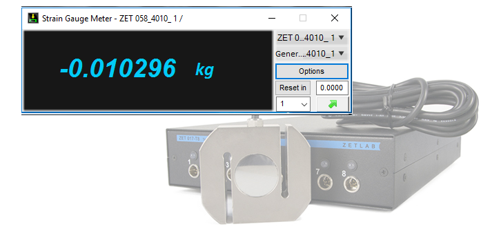
The program Strain gauge meter is intended for various strain gauge measurements with the use of strain gauge transducers (e.g., force and torque transducers, RPM sensors, bridge and half-bridge circuits based on strain gauges, etc.) and a measurement module for strain gauges ZET 017-T.
Depending on the parameters configuration of the Strain gauge meter program, the measurements results can be represented as force, weight, displacement, torque and other parameters. Integrated generator of the measurement module can be used for power supply of the transducers.
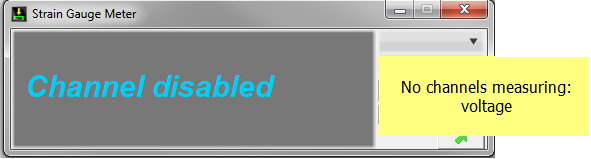
The program Strain gauge meter is compatible only with the input channels, which are used for voltage measurements. The measurement unit by default is V, or its derivatives. In the case, if the corresponding channels are not found, the drop-down list becomes unavailable and there appears the following notification:
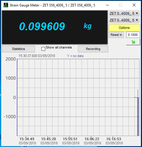
The program Strain gauge meter has an integrated signals recorder, which is used for displaying of the recorded data for the period of 60 minutes. It is also possible for the user to save the signals displayed on the graph to a file with *.dtx extension. If the program is used in multi-channel mode, then in order to display all the channels on the graph, it is necessary to enable the option Show all channels. For more convenience, the channels data is also available in chart form (the displayed parameters are as follows: max. and min. value, amplitude, average value and RMS value).
Strain-gauge meter program: parameters configuration
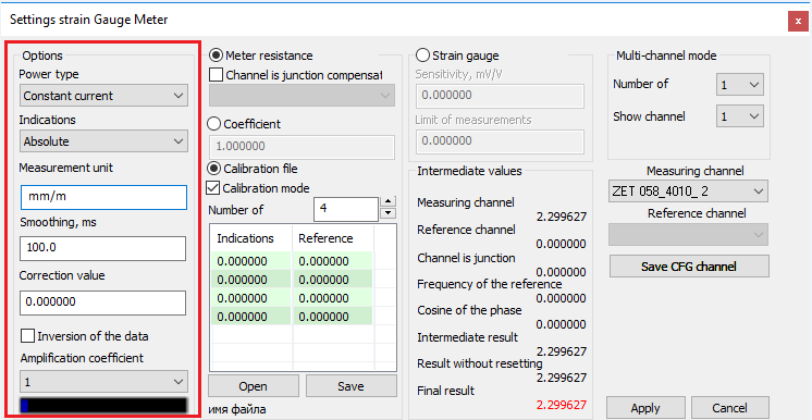
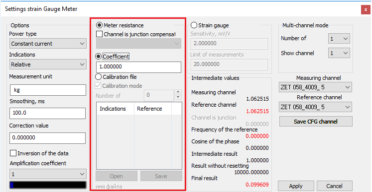
Configuration of the measurement channels parameters is performed in the dialog window “Settings Strain gauge meter”, which is activated with the key “Options” in the main window of the Strain gauge meter program.
The window “Settings Strain gauge meter” is separated into several sections, which are also available for configuration: “Options”, “Strain gauge”, “Intermediate values”, “Multi-channel mode” and the section displaying the channels used for configuration.
Parameters
The section “Options” is used for configuration of general parameters of the measurement suite:
- Power type – variants of power supply for the transducers from the integrated generator of the measurement module (constant or alternating current);
- Indications – absolute or relative. If the relative readings are selected, it is necessary to assign two channels: measuring channel and reference channel. In the case, if absolute readings are selected, the section “Reference channel” becomes unavailable;
- Measurement unit – the measurement unit to be displayed next to the numerical value. This parameter does not convert the measurement units and is used for informational purposes only;
- Smoothing, ms – the period in ms to be used for averaging of the measured values. The interval of a single measurement is 100 ms, hence, the averaging interval should be divisible by 100 ms;
- Correction value – the value, which is not to be taken into consideration in the case, is the key “Reset in” is active. This section displays the difference between the value specified in the filed “Reset in” and the current measurements results (i.e., if we set the reset value as “0” when the current measurement value is “3”, then the correction value will be “-3”);
- Inversion of the data – this option is used when it is necessary to obtain the results with opposite value;
- Amplification coefficient – amplification of the measurement channel in 1, 10, 100 or 1000 times. As the amplification coefficient value is changed, the signal integral level indicator will display the ratio of the input signal to the available measurement range of the strain gauge module.
Meter resistance
When a load-indicating resistor is used as a sensing element, the section “Meter resistance” is used for configuration of the corresponding parameters, and the “Strain gauge” section becomes unavailable.
The parameters also allow to assign the channel to be used for thermal compensation (i.e., to select the strain gauge to be used for temperature coefficient evaluation). The set value will be taken into consideration in the course of measurements performance.
For the load-indicating sensors, it is necessary to select the algorithm of the measurement process (i.e., to select Coefficient or Calibration file).
If there is a need to measure relative deformation, strain, or any other values having linear relation to the load-indicating sensors measurements, it is necessary to assign the Coefficient of load-indicating sensor sensitivity (the coefficient is calculated individually for each particular circuit).
In the case, if it is necessary to measure weight, force, and other physical values, which have non-linear dependence on the load-indicating sensor value, or it is difficult to calculate the sensitivity value, then it is possible to use the calibration chart for the conversion purpose. To do it, enable the option “Calibration file”. Then it is necessary to enter the load value and Strain-gauge meter value into the calibration file, or use already existing file with the calibration chart.
Upon activation of the “Calibration file” option, the user can switch over into Calibration mode by activation the corresponding option. The calibration mode implies the use of absolute values.
As the calibration mode is enabled, the indication color of the Strain gauge meter program changes (from blue to red).
The registered values correspond to the voltage level at the output of the strain gauge transducer. Thus, it is possible to conduct calibration of the sensing element by applying the reference value and recording the corresponding voltage level at the indicator of the Strain gauge meter.


The section Indications of the calibration chat can be filled automatically: right-click on the reference value and select the option “Use the indicator value”.
It is also possible to save the calibration chart for further use.
Upon completion of the calibration process, uncheck the option Calibration mode and save the changes by clicking Apply key.
Strain Gauge
If a strain gauge transducer is used as a sensing element, the parameters configuration is conducted in the corresponding section “Strain gauge”. In this case, the section “Meter resistance” becomes unavailable.
It is possible to use two parameters for configuration of the strain gauge transducers:
- Sensitivity, mV/V;
- Limit of measurements – the maximal value of the deformation, which can be registered by the transducer.
When the strain gauge sensor is used as a primary transducer, it is possible to calculate only relative values of the strain gauge meter.
Hence, it is necessary to use a reference channel in addition to the measurement channel.

The field “Intermediate values” is used for diagnostics of the sensing element operability.
It displays the values of the measurement channel, reference channel (in the case of strain gauge transducer there is used a channel of the generator), thermal compensation channel, reference channel frequency, phase cos., intermediate result, result without reset (actual values), final result (in the case of thermal compensation channel or Reset option use, the result will be displayed with consideration of these parameters, in other cases the result will be displayed without the Reset function).
Multi-channel mode
New version of the Strain gauge meter program has a function of Multi-channel mode.
If there is a need to implement a great number of primary transducers, it becomes necessary to control each of the channels simultaneously. Previously it was possible to do it by running several copies of the “Strain gauge meter” program, which was not always convenient. Now it is possible to display several channels by using a single copy of the program and by activating the Multi-channel mode.


The section “Multi-channel mode” allows to set the number of channels and to select a channel to be displayed for further configuration of its parameters.
To save the changes in parameters configuration, use the key “Save CFG channel” upon configuration completion for each of the channels.
Then use the “Apply” key to continue operation of the “Strain gauge meter” program.
Strain gauge meter program: prompt messages
In order to secure correct operation of the “Strain gauge meter” program, the system produces a number of prompt messages informing the user of the wrong parameters values. The developers of the program have conducted comprehensive analysis of the most frequent mistakes in the course of program operation. As a result, the program has the following notification messages:
- Reference channel not found – the message is formed in the case if relative indications are selected, but the reference channel is not assigned;
- Set the correct channels – the program produces this message in the case if measurement and reference channels have different sampling frequencies;
- Reference signal level below 3% of the upper range – the message recommends to select suitable reference channel.


Supported instruments
Source information of the Strain gauge meter program is represented by digital data from ZETLAB server channels. This data is formed by the output signals of the strain gauge transducers, tensile and compression gauges, bridge circuits. Measurement module ZET 017-T8 is used for digital processing of analog signals.
The Strain gauge meter program is included into Measurement software section.

The Strain gauge meter program is also included into ZETLAB TENZO Software package, which is delivered together with measurement modules for strain gauges.
Attention
Failure of the programs included into the scope of ZETLAB Software package may be attributed to electrical crosstalk. In order to check operational capacity of the device, establish Ethernet connection and start the corresponding programs. Detailed description of establishing Ethernet connection is available in user manual (to enter the user manual section, start ZETLAB control panel, press F1 key and select the clause “Connection via Ethernet”).
If the device and the program operate in normal mode, you can continue using Ethernet connection.