Automated engine testing system

Automated engine test system is intended for comprehensive testing of electrical motors with shaft rotation frequency up to 70 000 rpm. Such engines include:

  • high-voltage motors;
  • traction engines;
  • internal combustion engines;
  • AC motors;
  • DC motors;
  • synchronous engines;
  • asynchronous engines;
  • asynchronous engines with short-circuit rotor.

Application spheres

  • Engine parameters testing

    for conformance with applicable requirements

  • Assembly

    assembly quality control

  • Engine parameters configuration

  • Engine running-in and testing

  • Comprehensive testing

    of both new and reconditioned engines

  • Commissioning tests

  • Endurance testing

  • MTBF testing

System specifications

Parameter Sensor Measuring range Measurement uncertainty, max
Coolant temperature TC+ ZET 7120 10…90 °C 1,0 °C
Coolant pressure ZET 7112-A 0…5,5 bar 0,05 bar
Coolant consumption Flow sensor+ ZET 7180-I 0…20 m³/h 0,2 m³/h
Compressed air temperature TC+ ZET 7120 17…150 °C 1,0 °C
Compressed air pressure ZET 7112-A 0…13 bar 0,05 bar
Comressed air consumption Flow sensor + ZET 7180-I 0…4 m³/min 0,04 m³/min
Temperature of the tested item TC+ ZET 7120 60…180 °C 1,0 °C
Room air temperature TC+ ZET 7120 0…60 °C 1,0 °C
Shaft rotation frequency ZET 402 + ZET 7180-V 0…1200 Hz 0,1 Hz
Shaft rotation speed ZET 402 + ZET 7180-V 72000 rpm 1 rpm
Rotor (rotor gas support) displacement ZET 7150 0…5 mm 0,1 mm
Active power consumed by frequency converter, engine and generator Power sensor + ZET 7180-I 1…30 kW 0,5 kW
Reactive power consumed by frequency converter, engine and generator Power sensor + ZET 7180-I 1…100 kVA 1 kVA
Current consumption by frequency converter, engine and generator Current sensor + ZET 7180-I 5…900 A 1 A
Engine and generator power voltage Voltage sensor + ZET 7180-I 0…800 W 10 W
Frequency converter power voltage Voltage sensor + ZET 7180-I 220/380 W 2 W

Note

Sensors and measurement modules are selected individually based on system requirements.

Advantages of the system

Automated control
Display of information
Idication at the control area
Certified system
Comprehensive testing performance
Measurements accuracy
Emergency shutdown
Data reporting

Operating principles

The engine to be tested is placed into a protective casing to be further connected to the test engine. Rotation of the test engine causes rotation of the engine to be tested. The protective casing has ports for connection of circulating water supply, compressed air and temperature sensors (the measurement points are located in direct vicinity to the engine surface).

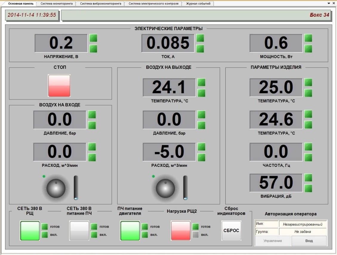
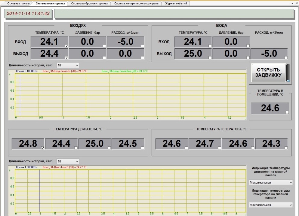
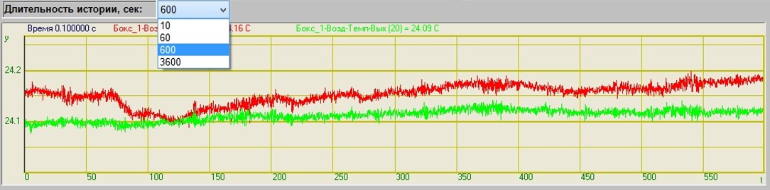
Temperature, pressure and flow sensors are installed at the input and output of cooling liquid and compressed air supply systems.

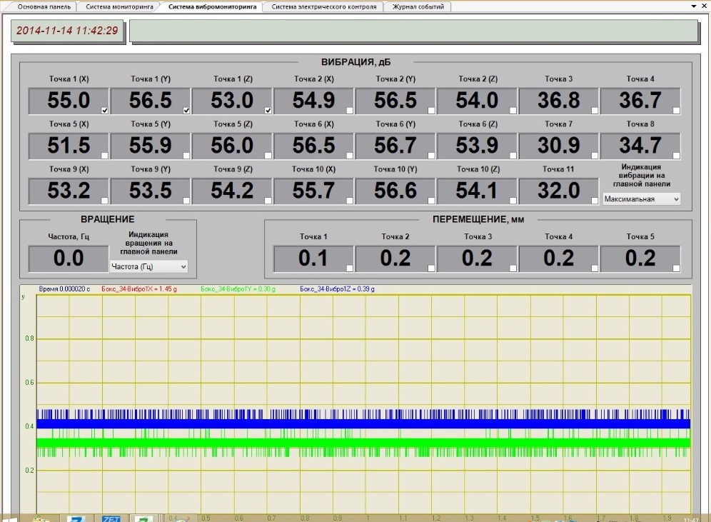
Current and voltage sensors are connected both to the test engine and the engine to be tested as well as to the generator and frequency converter. The vibration sensors are mounted on the test stand supports for the purpose of vibration level control of both test and tested engine.

In the course of system development, there are used digital sensors, consisting of primary transducers (with corresponding measurement units) and measurement modules to be used for processing of the signals received from the primary transducers. In the case of pressure and vibration sensors, the primary transducer and the measurement module are placed inside of a single casing, in other types of sensors they can be placed in separated casings interconnected with cables.

The measuring modules are sequentially connected to the measuring system with cables, thus, forming measurement branches with CAN 2.0 interface. The necessary amount of measurement branches depends on the quantity and location of the tested items.

Automated engine test system: structural scheme layout

The signals from the digital sensors are sent to the server for storage, further processing, and calculation of the necessary parameters to be displayed on digital indicators at the control areas and the WKS. Interface converters ZET 7174 (CAN↔USB) or ZET 7176 (CAN↔Ethernet/Wi-Fi) are used in order to provide data exchange between the WKS and the CAN 2.0 interfaces.

The server is used for data storage and data transfer to the WKS. The system may have several separate WKS-s – for instance, for control and monitoring purposes.

The automated system is also equipped with the control modules used for the control of the set threshold levels. Should the threshold values be exceeded, the system will provide an emergency shutdown of the test system power supply.

Automated WKS

Electrical motors and electrical drives operation control, as well as testing process control, is performed by means of 3 WKS-s.

Main control panel

Main control panel

Main control panel

The window “Main control panel” is used for the control of the following parameters:

  • electrical: voltage, current, power
  • test item parameters: item temperature, rotation frequency, vibration level
  • input and output air parameters from the air cooling system: input and output pressure, air intake.

It is also possible to control the position of the main valve of the air cooling system with a regulator and visually control the valve position.

In the case, if the set parameters threshold levels are exceeded, the operator automatically receives a notification with the corresponding message.

The main panel of the WKS contains the keys for power supply control in the course of tests performance and emergency shutdown of the system.

Monitoring subsystems

The monitoring subsystems are represented by a set of measurements related to pressure, temperature air and water flow control.

monitoring subsystem

monitoring subsystem

The upper section of “Monitoring system” window contains values of the controlled parameters – temperature  (°C), pressure (bar), flow (m³/min) at the input and output of the tested item cooling system.

It is also possible to display the controlled parameters of the cooling system in graphical format. The dropdown list allows to select the duration of the time history to be displayed.

vibration monitoring subsystem

Electrical control subsystem

The electrical control subsystem is a set of measurements related to the current and voltage level of the engine, generator and frequency converter.

electrical control subsystem

“Electrical control” subsystem depicts all the measured values of the controlled parameters: voltage parameters, phases, total power, active power, reactive power.

Vibration control subsystem

Vibration control subsystem is a set of measurements related to vibration, supports displacement, rotation frequency and temperature of the tested item.

vibration monitoring subsystem

Vibration monitoring subsystem depicts all the measured values of the controlled parameters: vibration (dB), displacement (mm), rotation frequency (Hz), rotation speed (rpm).

Events log

The “Events log” enables search and view of the events detected by the automated test system.

Events log

Server

The software of automated test system is based on ZETLAB and ZETVIEW software packages and allows to receive constant data flow from the registering and recording instruments as well as to send it to the WKS by Ethernet.

The server software allows to implement both constant and periodical remote control (without interruption of the data transfer function) as well as save the information of the system’s operability in the events log.

Service programs from the scope of ZETLAB Software enable remote configuration of any node of the system without the need to suspend connection of the server with the remaining nodes.

Order form - If you want to place an order or to make a request regarding technical specifications of particular product, fill out the form below:

Data protection notification

Please note that the personal data provided by you is used exclusively for the purposes of fulfilling our contractual obligations, including, but not limited to: issuing invoices, delivery documents, documentation relating to customs clearance process, etc. We do not provide your personal data to any third party except for the purposes relating to our direct contractual obligations. Upon completion of order processing and expiry of the warranty period for the Products provided by our Company, we do not store or process any of your personal data. Please note, that our Company’s Confidential policy does not imply any advertising or marketing activities with the use of your personal data (including your Company name, address, your E-mail, phone number and other information provided by you with a view to placing an Order and organization of the Delivery).