
Evaluation of vibration acceleration and frequency non-uniformity
It is possible to conduct the first stage of the calibration procedure in semi-automated mode.
To do this, start the SCADA-project, enter the Clause 4.5 “Evaluation of vibration acceleration and frequency non-uniformity”. The program interface is shown in the figures below.


It is possible to evaluate vibration acceleration and frequency non-uniformity at the frequency (fb * ft)1/2, where fb and ft — are the bottom and top border of the shaker system nominal frequency range or at the transition frequency between the reproduction of vibration displacement to vibration acceleration, or at the frequency of 400 Hz at the acceleration level of 0,7 from the the top level of nominal acceleration range.
Upon completion of the warm-up period it is necessary to measure acceleration and frequency level after each 15-20 minutes (unless otherwise specified in the standards and technical documentation) of the first hour, and then – every hour during the maximum possible period of system’s uninterrupted operation; to do this, save the current values of acceleration and frequency to the log once per hour by clicking “Add” button in the main dialog window of program’s interface.
Upon completion of the maximum possible shaker system uninterrupted operation period, the user can obtain a measurements protocol by setting its number and clicking the key “Save the report”.
In the case, if you do not have the task-specific software “Shaker systems calibration”, you can perform all the necessary measurements using ZETLAB Software package. The program “DC voltmeter” is used for the purpose of vibration acceleration measurements (figure 1)
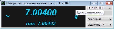
Figure1. “AC voltmeter” program: vibration acceleration measurements
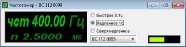
Figure 2. “Frequency meter” program: signal frequency measurements
In accordance with the applicable standards, for the purpose of vibration acceleration non-uniformity control, it is recommended to use operation mode with the automated sweep of the signal (in the case if such mode is available) and maintenance of the set acceleration level at the control point. The system for vibration exciters calibration provided by ZETLAB Company includes such mode in the case if the user has the shaker controller (in our particular example – VCS ZET 017-U). To use it, turn on the VCS ZET 017-U, start the program “Feedback generator (Sinusoidal vibration)”, set the frequency range, necessary acceleration level and sweep time (or velocity).
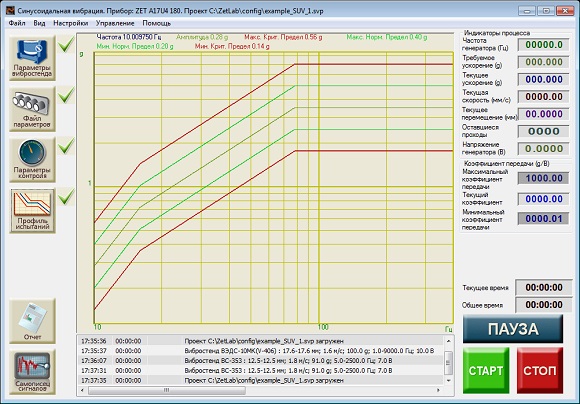
Figure 3. “Feedback generator (Sinusoidal vibration)” program
In this case, the frequency sweep range should be equal to the nominal frequency range, while acceleration and displacement should be 0,7 from the top level of the nominal ranges limit. If the frequency sweep rate is from 0,5 up to 1,0 octave per minute during the maximum possible duration of shaker system’s uninterrupted operation, then the acceleration value is measured at the transition frequency or at 400 Hz frequency at equal time intervals specified above. The program “Feedback generator (Sinusoidal vibration)” automatically maintains the set acceleration value at the control point throughout the frequency range.
The program “Feedback generator (Sinusoidal vibration)” can be used for producing the signal with an automated frequency sweep. The program also allows to set a complex test profile (figure 5) with the maintenance of the set displacement value at low-frequency range, velocity at medium frequency range, acceleration at the high-frequency range.
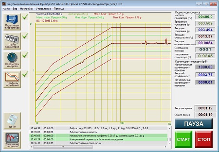
Figure 4. The program “Feedback generator (Sinusoidal vibration)”. Tests process
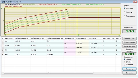
Figure 5. Vibration tests profile
It is also preferable to use the automated frequency sweep mode since it allows to evaluate vibration acceleration non-uniformity in the dynamic operation mode of the vibration exciter (shaker) as the specified frequency range is approached by the signal. When using the program “Feedback generator (Sinusoidal vibration)” in the calibration procedure, it is also convenient to use the function “Signals recorder” for producing the test report. This function enables tracking the changes of frequency and acceleration values of the reference transducer in the course of tests performance (figure 6). It is also possible to view linear representation of the frequency graph by switching the graph vertical axis into the logarithmic scale (figure 7).
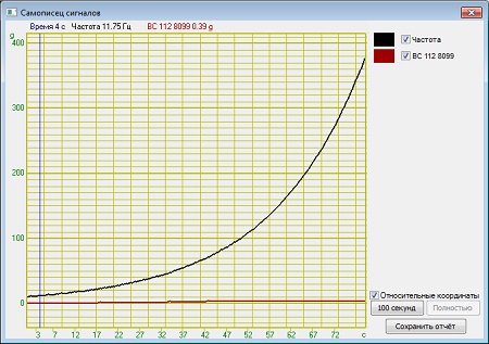
Figure 6. “Signals recorder” program, frequency graph
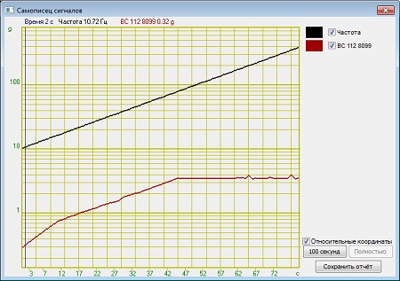
Figure 7. “Signals recorder” program, linear frequency graph
It is also convenient to use the program “Multichannel recorder” for evaluation of vibration acceleration and frequency non-uniformity in statical mode (i.e. in the case when a constant-frequency sine signal is applied to the input of the vibration exciter (shaker)). Figure 8 shows two different examples acceleration measurements for the vibration transducer. Measurements interval: 1 second.
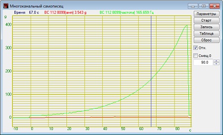
Figure 8. “Multichannel recorder” program
In the case of periodical calibration, it is allowed to conduct measurements during a time period of 50% from the maximum possible time of shaker system uninterrupted operation.
Acceleration non-uniformity in percentage rate is calculated by the following formula:
where ac and as — stand for the current and the set value of acceleration at the control point.
Frequency non-uniformity in percentage rate is calculated by the following formula:
![]()
where fc and fs — stand for the current and the set value of the frequency at the control point.
See also:
- Shaker calibration system
- Test-run of the shaker system
- Evaluation of vibration acceleration, vibration displacement, and frequency range
- Evaluation of acceleration and/ or displacement harmonics ratio
- Calculation of lateral components ratio
- Calculation of distribution non-uniformity ratio
- Calculation of trunnion resonance frequency and the first resonance frequency of the system
- Evaluation of the shaker table vibration noise level
- Evaluation of the tolerance limit for maintenance of the acceleration and/ or displacement level at the control point
- Evaluation of the tolerance limits for reproduction of acceleration and displacement level at the control point