
Evaluation of acceleration and / or displacement harmonics ratio
It is possible to conduct this stage of the calibration procedure in automated mode.
To do this, start the SCADA-project, enter “Clause 4.7. “Evaluation of acceleration and displacement harmonics ratio”. The program interface is shown in the figures below.


In order to start measurements process it is necessary to set the nominal characteristics of the vibration exciter (shaker) and start the calibration procedure:
- assign the measuring channel of the transducer, installed at the shaker table as the control channel;
- set the bottom and upper limit frequency value in accordance with the shaker data sheet;
- set the values of nominal displacement and nominal acceleration in accordance with the parameters specified in the datasheet of the shaker;
- in the drop menu “Load value” select “No load”, enter “0” in the text field;
- start measurement process by clicking “Calibration” button;
- in the case if there is a need to perform load testing, use the load of 25% from the nominal value of the shaker; in the drop menu “Load value”, select “0,25 of the nominal load”, enter the corresponding value in the text field; start the measurements process by clicking the “Calibration” button;
- upon completion of measurements process, enter corresponding data in the text field “protocol number”, save the calibration protocol by clicking “Save report” key.
In the case, if the software “Shaker calibration” is not available, it is still possible to conduct all necessary measurements using ZETLAB software package. The acceleration and/or displacement harmonics ratio are evaluated in the nominal frequency range at the upper limit of acceleration and (or) displacement ranges by means of the program “Non-linear distortion analysis”.
The program “Multichannel oscilloscope” is used for control of acceleration and displacement graph.
Using the program “Signal generator” it is possible to calculate the displacement harmonics ratios (at generator frequency level below 50 Hz) and acceleration harmonics ratios (at generator frequency level over 50 Hz).
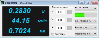
Figure 1. “Vibration meter” program
In order to calculate displacement harmonics ratio, double-integer the acceleration signal in the program “Vibration meter”. Start the program “Vibration meter”, set the band filter range “3.0 – 10 000.0 Hz”, measurement method – “Amplitude”, averaging time – “1 second” (figure 1).
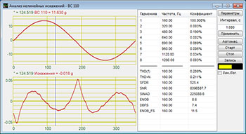
Figure 2. “Non-linear distortion analysis” program
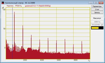
Figure 3. “Narrowband spectrum” program
“Frequency meter” program is used for the purpose of the reference vibration transducer frequency control. “Multichannel oscilloscope” program is used for the reference vibration transducer frequency curve control. The program “Narrowband spectral analysis” (figure 3) allows to observe the carrier frequency of the signal and corresponding harmonics. The program “Non-linear distortion analysis” (figure 2) is used for calculation of ratios for each harmonic, estimation of the true signal shape and distortions.
The program “Non-linear distortions analysis” is used for control of a number of signal’s parameters. For the purposes of vibration exciter (shaker) calibration, set the harmonic distortion ratio “THD(f)”.
See also:
- Shaker calibration system
- Test-run of the shaker system
- Evaluation of vibration acceleration and frequency non-uniformity
- Evaluation of vibration acceleration, vibration displacement, and frequency range
- Calculation of lateral components ratio
- Calculation of distribution non-uniformity ratio
- Calculation of trunnion resonance frequency and the first resonance frequency of the system
- Evaluation of the shaker table vibration noise level
- Evaluation of the tolerance limit for maintenance of the acceleration and/ or displacement level at the control point
- Evaluation of the tolerance limits for reproduction of acceleration and displacement level at the control point