
Shaker test run
The test run of the shaker system is performed by its activation in no-load mode, sending an AC current signal to the shaker system and its subsequent shut-down without any load applied to the shaker system table.
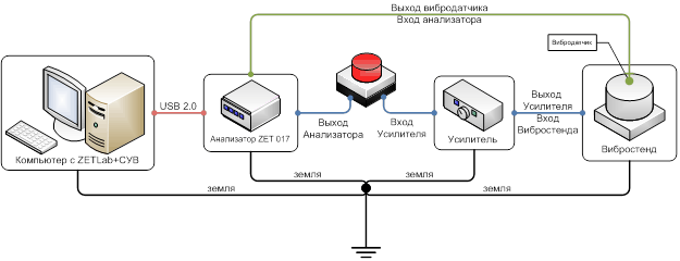
Figure.1. Connection diagram and components grounding layout
Proper operation of the shaker and the generator is controlled “by ear” – one should hear a monotonic sound.
Prior to the beginning of the test run, it is necessary to double-check absence of the line interference (50 Hz) using the “Narrowband spectrum” program as well as the proper grounding of the instruments used.
The graph distinctly shows the absence of a clear peak at 50 Hz (i.e., the line interference) and corresponding harmonics. In the case, if the line interference is revealed, one should double-check proper grounding of the measuring system (FFT Spectrum analyzer) and other components of the system.
The program “AC voltmeter” is used for the purpose of noise level and shaker system acceleration evaluation. Using this program, it is also possible to estimate overall noise level by selecting proper frequency range in the settings.
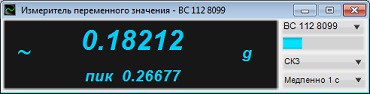
Figure 2. “AC voltmeter” program
After having evaluated the noise level, it is necessary to check the operability of the vibration transducers by knocking at the shaker system table. The program “Narrowband spectrum” allows to reveal the presence of tone signals and noise components in the measuring channel based on the spectrum curve shape.
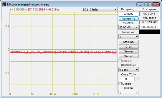
Figure 3. Multichannel osciloscope: no signal
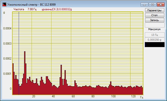
Figure 4. Narrowband spectrum: spectrum without signal
The next stage of the test run is sending the test signal from the output generator to the input of vibration exciter amplifier. In order to set the signal parameters, start the program “Signals generator”, activate low-level sine signal, so that to avoid overloading of the shaker system and its amplifier (e.g., 50 mV, 1000 Hz).
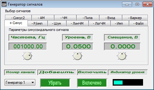
Figure 5. “Signals generator” program
The program “Multichannel oscilloscope” allows to evaluate the shape of the reproduced signal by means of the reference transducer and to compare it with the signal at the output of the FFT spectrum analyzer.
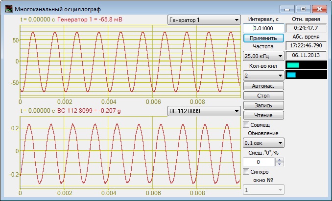
Figure 6. “Multichannel oscilloscope” program window
The upper graph (Figure. 6) shows the signal shape of the virtual generator – an ideal sine signal. The bottom graph depicts the signal shape from the reference vibration transducer attached to the shaker table.
See also:
- Shaker calibration system
- Evaluation of vibration acceleration and frequency non-uniformity
- Evaluation of vibration acceleration, vibration displacement, and frequency range
- Evaluation of acceleration and/ or displacement harmonics ratio
- Calculation of lateral components ratio
- Calculation of distribution non-uniformity ratio
- Calculation of trunnion resonance frequency and the first resonance frequency of the system
- Evaluation of the shaker table vibration noise level
- Evaluation of the tolerance limit for maintenance of the acceleration and/ or displacement level at the control point
- Evaluation of the tolerance limits for reproduction of acceleration and displacement level at the control point