
Calculation of lateral components ratio
This stage of calibration procedure can be performed in automated mode.
To do this, start the SCADA-project, “Clause 4.8 “Evaluation of lateral components ratio”. The program interface is shown in the figures below.


In order to start measurements process, it is necessary to set the nominal characteristics of the vibration exciter (shaker) and start the calibration procedure:
- assign the measuring channels of the three-component accelerometers or the transducers, mounted on the planes of the cube;
- set the bottom and upper limit frequency value in accordance with the shaker data sheet;
- set the values of nominal displacement and nominal acceleration in accordance with the parameters specified in the datasheet of the shaker;
- in the drop menu “Load value” select “No load”, enter “0” in the text field;
- start measuring process by clicking “Calibration” key;
- in the case if there is a need to perform load testing, use the load of 25% from the nominal value of the shaker; in the drop menu “Load value”, select “0,25 of the nominal load”, enter the corresponding value in the text field; start the measurements process by clicking the “Calibration” button;
- upon completion of measurements process, enter corresponding data in the text field “protocol number”, save the calibration protocol by clicking “Save report” key.
In the case if you do not have the software “Shaker calibration”, then it is possible to conduct corresponding measurements using ZETLAB software package
Three-component accelerometers (figure 2) are used for the purpose of lateral components ratio calculation.
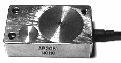

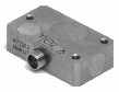
Figure 2
It is also possible to use single-component vibration transducers set in three mutually transverse directions at the planes of the vibration transducers or at planes of the mounting cube. The resonance frequency of the mounting cube can be calculated by the formula fр = 800 / L, where L is the length of the cube face in mm. The obtained value of cube’s resonance frequency should not exceed the top limit of the shaker nominal range more than in 1,5 times.
The lateral components ratio is calculated in nominal frequency range at constant acceleration values and (or) at displacement values over 30% from the upper limit of the nominal acceleration ranges and (or) shaker displacement value.
The “Multichannel oscilloscope” program is used for the purpose of the three-component (in our particular example) vibration trnaducer signal control. Figure 3 shows oscillograph charts for X, Y and Z components of the vibration transducer (in reverse order) for 1100 Hz sinusoidal signal. X and Y components are mutually transverse to each other and to the shaker system axis. Z component is parallel to the shaker system axis.
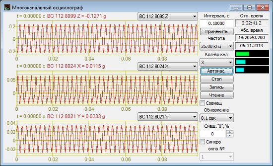
Figure 3. “Multichannel oscillocope” program – analysis of three-component vibration transducer signal.
The “AC voltmeter” program is used for the analysis of vibration acceleration. Figures 4,5 and 6 show acceleration values for X, Y and Z components (from the left to the right).
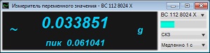
Figure 4
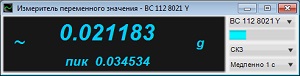
Figure 5
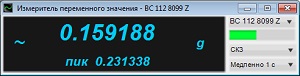
Figure 6
The lateral components ratio of the vibration transducer is calculated based on measurements results at three mounting points as the maximum obtained value for all the mounting points. The lateral components ratio Kl for each mounting point in this operating mode is calculated by the formula:
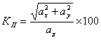
where ax and ay stand for acceleration and (or) displacement value in two directions transverse to each other and to the shaker axis; az — acceleration and (or) displacement along shaker system axis.
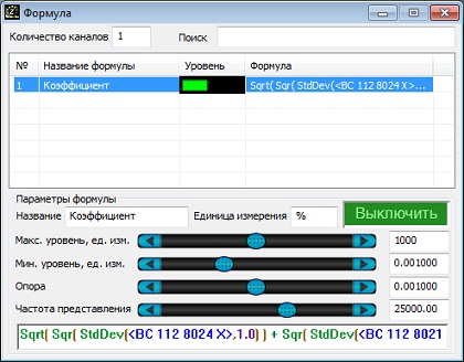
Figure 7. “Formula” program – creation of a rormula for calculation of transverse components ratio
The value of the obtained ratio can be viewed in the program “DC voltmeter”. Upon completion of calculations by this formula, the lateral components ratio value was 25%. The obtained value meets the applicable requirements stating that the upper limit of the nominal frequency range at corresponding load should not exceed 25%.
See also:
- Shaker calibration system
- Test-run of the shaker system
- Evaluation of vibration acceleration and frequency non-uniformity
- Evaluation of vibration acceleration, vibration displacement, and frequency range
- Evaluation of acceleration and/ or displacement harmonics ratio
- Calculation of distribution non-uniformity ratio
- Calculation of trunnion resonance frequency and the first resonance frequency of the system
- Evaluation of the shaker table vibration noise level
- Evaluation of the tolerance limit for maintenance of the acceleration and/ or displacement level at the control point
- Evaluation of the tolerance limits for reproduction of acceleration and displacement level at the control point