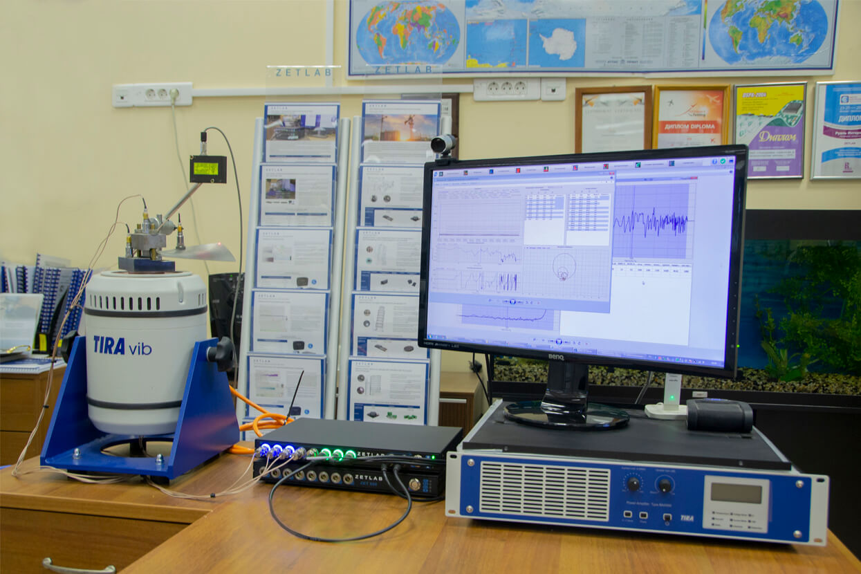
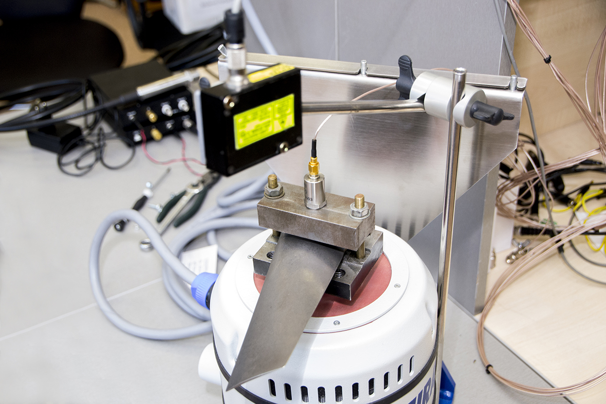
System for fatigue testing of the turbine blades
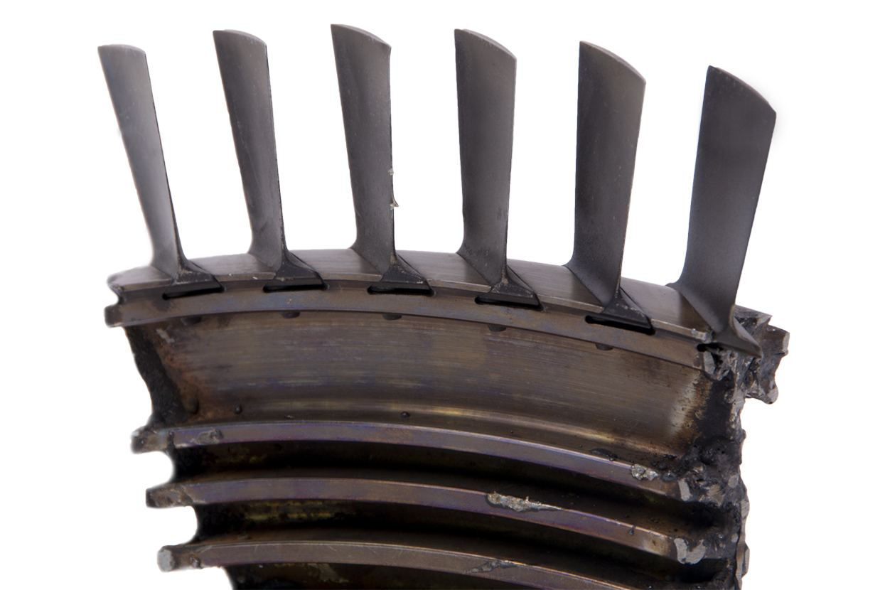
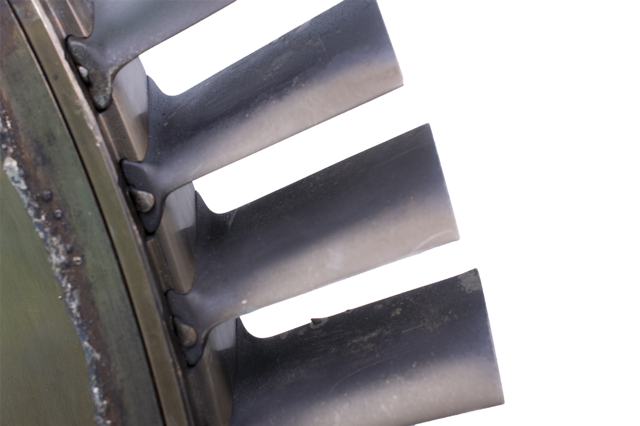
Blades of steam and gas turbines are exposed to considerable loads, hence, their operational condition directly affects the long-term performance of the machinery. The turbine blades parts make up about 50% of the entire turbine machinery components. It means, that the main task in terms of reliability increase is the control of turbine blades operational characteristics at the stage of their manufacturing.
The system for fatigue testing of the turbine blades allows to conduct tests in full compliance with the applicable requirements and in automated mode, which allows to spend less time and labour resource for the tests implementation, as well as to enhance the accuracy of measurements performance.
Basic configuration of the system
| Basic configuration | |||
|---|---|---|---|
| Item | Designation | Amount | Price |
| Shaker (vibration exciter) | generation of vibrational impact | 1 | POR |
| Power amplifier | amplification of the signal sent from the controller to the shaker system | 1 | included into the delivery scope |
| Displacement transducer | turbine blade displacement control | 1 | POR |
| Accelerometer BC 111 | reference vibration transducer | more than 1 | POR |
| Shaker controller ZET 024 | control of the vibration testing performance, recording and control of the signals received from the primary transducers | 1 | POR |
| Software package: Option “Resonance search, track and dwell (RSTD)” Option “Random-on-random (ROR)” Option “Sine-on-sine” “Kurtosis” option |
software for evaluation of the turbine blades size | 1 package | POR |
| PC or laptop | upon request | 1 | POR |
| Additional configuration | |||
| Strain gauge transducer | control of the turbine blade’s stress-strain condition | more than 10 | POR |
| Strain-gauge amplifier ZET 052 | amplification and conversion of the input signal received from the strain gauge transducers | 1 | POR |
| Eddy current AE transducer | additional control of the turbine blade displacement | 1 | POR |
| Accessories:
magnetic mounting AM 50 |
for mounting of the accelerometers vibration measurements in three mutually transverse directions for mounting of the accelerometers for isolation of the conductive surfaces |
1 1 1 1 |
POR |
*Transducer of this type allows to register displacement at the resonance frequencies up to 1500 Hz. In the case if the resonance frequency is more than 1500 Hz, then the transducer is to be selected on individual basis upon order placement.
The cost of the system is calculated on individual basis upon order placement
Operating principle
Operating principle of the system for fatigue testing of the turbine blades is based on maintenance of the specimen’s sampling frequency and tracking of its dynamics.
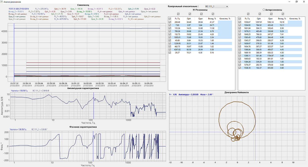
Prior to tests performance, it is necessary to run the program “Pre-test and control” for preliminary analysis of specimen’s dynamic characteristics and selection of the most suitable control transducer. Based on the results of the pre-test, the software registers all resonances and anti-resonances occurring in the specimen.
The user can select the resonance frequency of the system, and start the testing with resonance value maintenance. Control of blade’s displacement amplitude is implemented with the use of laser transducer.
Accumulation of the fatigue damage will eventually result in change of the turbine blade’s resonance frequency. Task-specific software “Resonance search, track and dwell (RSTD)” allows to track this shift and to accordingly adjust system parameters in automated mode.
There are several methods used for fatigue testing of the turbine blades:
- standard;
- accelerated with constant voltage amplitude;
- accelerated with increasing voltage amplitude.
The standard method allows to estimate the strength reserve of the turbine blade based on averaged fatigue curve and the relevant endurance limit. In order to implement testing based on this scenario, it is necessary to use a production lot of 15-30 pcs.
Accelerated test methods are used for evaluation of endurance limit for a particular test configuration and at a particular number of cycles required for evaluation of the averaged fatigue curve parameters, and for evaluation of averaged values, endurance dispersion value and strength limits.
Accelerated test methods with constant amplitude include the probability units method, ladder method and the standard method used for accelerated evaluation of the endurance limit. The tests are conducted at constant pre-set voltage amplitudes throughout the entire cycle of the turbine blade fatigue testing. Each turbine blade is tested only at a particular voltage amplitude.
Accelerated test methods with increasing voltage amplitude include the method with stepwise load increase, Pro method, and Locati method. These tests are conducted at constant voltage amplitudes with the subsequent overloading of the integral blade up to the next voltage amplitude, thus, the voltage amplitude is gradually increasing throughout the entire testing process (whether in constant, or in stepwise manner).

