Metrological self-check
Nowadays intelligent sensors as well as intellectual measuring systems are intensively developed and widely applied all over the world.
There is a great variety of national and international standards that are applicable to intelligent sensors and intellectual measuring systems.
We are going to use the following terms and definitions:
Smart sensor – adaptive sensor with metrological self-check option.
Metrological self-check of the sensor – automated check of sensor’s metrological operability in the course of its use. The automated checking is performed by means of reference value obtained from an integrated (measuring transducer) or an external (additional output channel parameter) device.
There are two types of the metrological self-check implementation: direct metrological self-check or diagnostic self-check.
Sensor’s direct metrological self-check – is a metrological self-check of the sensor performed by means of evaluation of measured value deviation from the reference value produced by an integrated device (measuring transducer) having a higher measurements precision.
Sensor’s diagnostic metrological self-check – is accomplished on the basis of evaluating a deviation of the parameter characterizing a critical uncertainty component from an accepted reference value of this parameter.
In accordance with the applicable requirements the metrological self-check is used to:
- reduce the possibility of obtaining unreliable measurements values during inter-verification and inter-calibration intervals
- to justify inter-verification and inter-calibration intervals duration depending on the remaining metrological operation time
- to reduce operational costs relating to the technological processes adjusments attributed to metrological failures.
The metrological self-check can be implemented in in-place mode (in this case there is no need to suspend the measurements process) or in test mode based on structural, time or functional redundancy.
In order to select the optimal way of performing the metrological self-check it is necessary to analyze all the factors relating to sensor’s error: to find the possible sensor error factors and related error components as well as to determine critical uncertainty component.
When analyzing the possible error factors it is necessarry to study operational examples of similar products, corresponding errors reasons, to find out the “weak links”. It is also necessary to study the expected operational environment conditions, design and manufacturing technologies of the measuring instrument being developed.
In order to calculate critical uncertainty component it is necessary to estimate the error’s development speed and error’s structural components, arrange the error’s components by relevance.
Metrological self-check system:
implementation examples
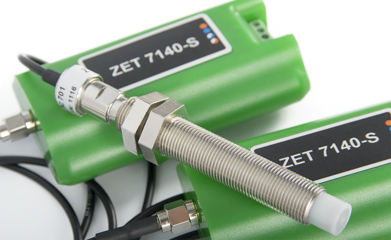
Direct metrological self-check of the eddy-current distance sensor (used to measure the distance to the conductive surface) can be implemented in test mode based on structural redundance principle. The sensor contains reactive inductive coil, receiving coil and a dummy element (i.e. flat inductive coil). The dummy element is placed in front of the target. The part which fixes the distance between the inductive coil and a dummy element is used for distance measurements.
Direct metrological self-check of the temperature sensor with resistance thermometer can be implemented on the basis of time and functional redundance. Thermometer’s resistance and noise spectrum parameters depend on the temperature value. Temperature measurements by noise spectrum are more precise than those based on resistance. Hence, we can use the temperature value measured by noise spectrum as a reference value.
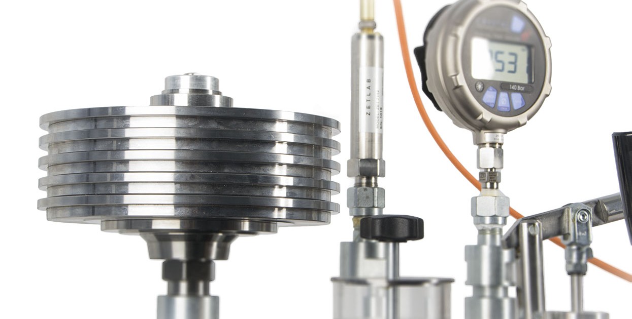
Metrological diagnostic self-check of the membrane pressure sensor can be implemented on the basis of structural redundance in test mode. In the sensors of this type the membrane is firmly attached to the plunger. The output signal is formed by plunger’s displacement inside of the inductive converter. The sensor also contains an electrical magnet – its coil is wrapped around the plunger.
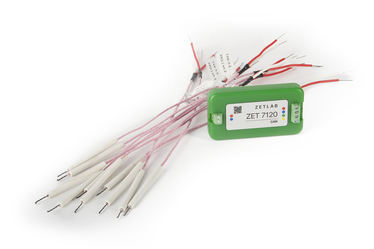
Metrological self-check of thermoelectrical temperature sensor can be implemented based on structural redundance principle. The sensor contains several thermocouples having almost identical precision rate. As a sensor transducer function we can use the dependence of thermocouples output signal average value on the measured temperature value.
Metrological self-check function is implemented in digital sensors of ZETSENSOR series with CAN 2.0 data transfer interface:
ZET 7110 – digital strain gauge sensor for statical measurements;
ZET 7110-DS – digital sensor for small deformations measurements;
ZET 7111 – digital strain-gauge sensor for dynamic measurements;
ZET 7120 – digital temperature sensor (primary transducer type – thermocouple);
ZET 7121 – digital temperature sensor (primary transducer type – thermal resistance);
ZET 7123 – digital meteorological sensor;
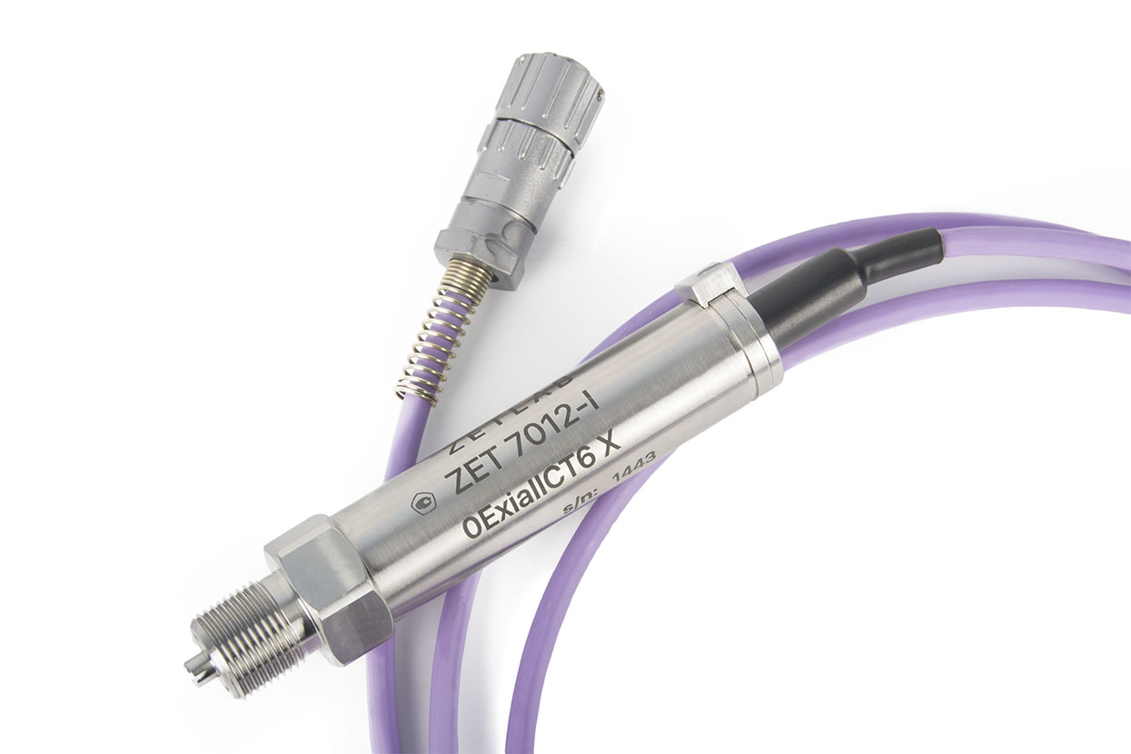
ZET 7112-I – digital gauge pressure;
ZET 7112-A – digital pressure meter;
ZET 7150 – digital seismic sensor;
ZET 7151 – digital accelerometer;
ZET 7152-N -digital accelerometer with an integrated primary transducer;
ZET 7152-E – digital accelerometer with an integrated primary transducer and an extended measurements range;
ZET 7155 – digital geophone;
ZET 7140-E – digital acoustic emission sensor;
ZET 7140-R – digital cavitation sensor;
ZET 7140-S – digital eddy-current displacement sensor;
ZET 7111-L – digital LVDT sensor;
ZET 7154 – digital tilt meter;
ZET 7160-E – digital encoder;
ZET 7180-I and ZET 7180-V– measuring modules;
ВС 314-М – cut-in geophone with digital output.
Metrological self-check: ZETSENSOR
Software
A special task-oriented software has been developed for automated metrological self-check of digital sensors of ZETSENSOR series.
In the figure you can see the main window of the program. “Metrological self-check” allows the user to select device type, test procedure as well as to control measurements process and to obtain self-check results.
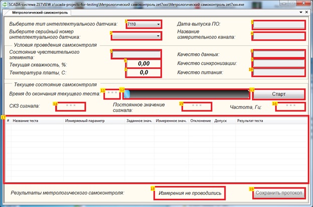
The drop-down list enables selection of intelligent sensor type (1). When the metrological self-check program is active, the value of the selector (1) can not be changed until the user stops project operation or until the self-check procedure is finished.
As the device type is selected, the element (2) will depict a list of the intelligent sensors of the corresponding type, which are connected to the PC. This selector is used to choose a particular intelligent sensor for the self-check procedure (the drop-down list allows to find the necessary serial number of a particular sensor). When the metrological self-check program is active, the value of the selector (2) can not be changed until the user stops project operation or until the self-check procedure is finished.
When the intelligent sensor is assigned, the program automatically retrieves information of the particular device. Thus, fields (3) – (10) are filled. In the case in the selected intelligent sensor does not have a sensing element or its board temperature can not be measured, field (5) or (7) will depict the following: «***».
To start or suspend the program operation, use the key (13). In the course of the metrological self-check performance the indicator is green, when the procedure is suspended, it becomes grey.
Elements (11)-(16) are used for metrological self-check process indication. Indicator (11) is a timer displaying the remaining time of the current test performance – this section will be filled with data in the course of the metrological self-check performance.
Indicators (14)-(16) are disabled by default. Indicator (14) becomes active in the case it is necessary to measure signal’s RMS (it will depict the current RMS value). Indicator (15) becomes active in the case it is necessary to measure signal’s constant value (it will depict the current constant value of the signal). Indicator (16) becomes active in the case it is necessary to measure signal’s frequency (it will depict the current frequency value).
Test results are shown in the log (17). The log contains the following data:
- test number;
- test name;
- measured parameter;
- set value of the measured parameter;
- actual value of the measured parameter;
- actual deviation of measured parameter;
- allowed deviation value;
- final result of test performance.
Test impact types
AC - alternating signal
FR: «Required frequency value»: «Frequency tolerance» – alternating signal frequency;
AM: «Required signal amplitude value»: «Signal amplitude tolerance» – alternating signal amplitude;
OF: «Generated signal bias»: «Generated signal bias tolerance» – generated signal bias;
TM: «Signal analysis time» – signal control time (minimal signal analysis time for transient processes or long-time tests)
Example:
AC;FR:0.5:0.01;AM:0.4:0.002;OF:0.1:0.0001;TM:5 –
Alternating signal with frequency: 0.5 ± 0.01 Hz, amplitude: 0.4 ± 0.002 V, bias: 0.1 ± 0.0001 V, minimal signal control time – 5 s.
Test performance:
As the test timer reaches zero, the following measurements will have been performed:
- Narrow-band spectral analysis will determine the frequency value – it will be displayed at the indicator (16).
- DC voltmeter will calculate the signal RMS – the value will be shown at the indicator (14).
- DC voltmeter will calculate the signal’s constant value – it will be displayed at the indicator (15) and saved to the log.
- There will be calculated a duty cycle trimming ratio of the signal.
Tests results are saved to the log. In the case if the values obtained comply with the test signal parameters range and duty cycle trimming value is within 30-70%, the test is considered to be passed.
DC - constant signal
LE: «Required signal level»: «Signal level tolerance» – generated signal level.
TM: «Signal analysis time» – control signal time (signal analysis minimal time for transient and long-time processes tests)
Example:
DC;LE:0.5:0.001;TM:5 –
constant signal: 0.5 ± 0.001 V, minimal signal control time – 5 s.
Test performance.
As the test timer reaches zero, the DC voltmeter will calculate the signal’s constant value – it will be displayed at the indicator (15) and saved to the log. Then, if the value obtained complies with the test signal parameters range and the duty cycle trimming value is within 30-70%, the test is considered to be passed.
ST1 - stepwise change
AM: «Minimal value»: «Maximum value» – change range.
TM: «Signal setting time» – time before signal control start
Example:
ST1;AM:100:200;TM:5 –
stepwise change: for 100..200 units, minimal signal control time – 5 s.
Test performance.
The device disables the test mode, after that signal’s constant value is measured (this allows to set the tolerance range limits) by means of the DC voltmeter. After that the device is switched over into a particular test mode. As the test timer reaches zero, the DC voltmeter will calculate the signal’s constant value – it will be displayed at the indicator (15) and saved to the log. Then, if the value obtained complies with the test signal parameters range and the duty cycle trimming value is within 30-70%, the test is considered to be passed.
ST2 - stepwise change
MD: «Minimal change»: «Maximum change» – change range.
TM: «Signal setting time» – time before signal control start
Example:
ST2;MD:10:10.5;TM:6 –
Stepwise change: 10..10.5 in modulus, minimal signal control time – 6 s.
Test performance.
The device disables the test mode, after that signal’s constant value is measured (this allows to set the tolerance range limits) by means of the DC voltmeter. After that the device is switched over into a particular test mode. As the test timer reaches zero, the DC voltmeter will calculate the signal’s constant value – it will be displayed at the indicator (15) and saved to the log. Then, if the value obtained complies with the test signal parameters range and the duty cycle trimming value is within 30-70%, the test is considered to be passed.
PPS - Pulse-per-second signal
SP: «Counts acceptable deviation» – amount of counts before or after start of a second.
Level change to be checked one time in a second.
Example:
PPS;SP:2 –
the change should take place in the beginning of a second, 2 counts.
Test performance.
As the test timer reaches zero, the measured deviation value will be recorded and saved to the log. The test is considered to be passed in the case if:
- the value obtained complies to the test signal parameters within the tolerance range;
- duty cycle trimming ratio of the signal is within 30% – 70%;
- signal frequency is within the range of 0,4 Hz – 0,6 Hz.
Otherwise the test is considered to be failed and the diagnostics process is stopped.
In the course of its operation the program sets the sensor parameters in accordance with a particular test – after that the program starts performing necessary measurements. The program compares actual signal of the measuring channel to the described signal and saves the measurement results to a log.
As the metrological self-check procedure is finished, the field (18) depicts metrological self-check results, and the key (19) becomes active. The key (19) is used to produce a protocol of the metrological self-check results.
Upon completion of the protocol formation there will appear an .xlsx file (in the folder with the run file «Metrological_Selftest_7xxx.exe»). This file contains a self-check procedure protocol, which is to be further forwarded to ZETLAB Company.
