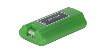
ZET 7140-R Digital Cavitation Sensor


- Data transmission interface CAN 2.0
- Amplification 10
- Input range ±100 mV
- AD converter bit depth 14 bit
From 1602 USD
Specifications
of the ZET 7140-R Digital Cavitation Sensors
| Metrological Data | |
|---|---|
| Rated sensitivity | 22 µV/Pa |
| Frequency band | 3 ~ 160 000 Hz |
| Technical Specifications | |
| Socket type for connecting a primary transducer | SMA |
| Measured parameter | RMSD of the signal from the primary transducer |
| Data output frequency | 1, 10, 100 Hz |
| Measurement range | depends on type of the primary transducer |
| Data transmission interface | CAN 2.0 |
| Amplification | 10 |
| Input range | ±100 mV |
| AD converter bit depth | 14 bit |
| Sampling rate | 1.2 MHz |
| 4 kV electrostatic discharge input protection | yes |
| Inputs overvoltage protection (current shall not exceed 10 mA) | yes |
| Performance Specifications | |
| Dimensions | 83×37×14 mm |
| Weight | 40 g |
| Power supply | 9 to 24 V |
| Consumed power | 1.5 W |
| Operational temperature range | -40 to +100 °С |