Evaluation of vibration acceleration, vibration displacement and frequency range
It is possible to conduct this stage of calibration in automated mode.
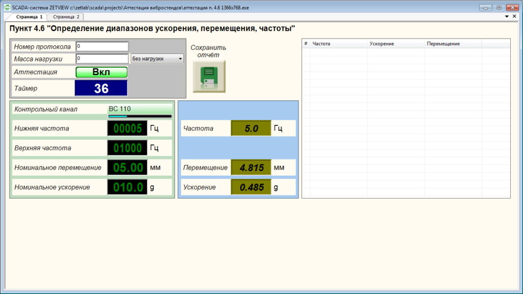
To do so, start the SCADA-project, select the section “Clause 4.6 “Evaluation of vibration acceleration, vibration displacement, and frequency range”. The program interface is shown in the figures below.
Prior to the start of measurements procedures, it is necessary to set the nominal characteristics of the vibration exciter (shaker) and start the calibration process:
- assign the measuring channel of the transducer, installed at the control point as the control channel;
- set the bottom and upper limit frequency value in accordance with the shaker data sheet;
- set the values of nominal displacement and nominal acceleration in accordance with the parameters specified in the datasheet of the shaker;
- in the drop menu “Load value” select “No load”, enter “0” in the text field;
- start measurement process by clicking “Calibration” button;
- in the case if there is a need to perform load testing, use the load of 25% from the nominal value of the shaker; in the drop menu “Load value”, select “0,25 of the nominal load”, enter the corresponding value in the text field; start the measurements process by clicking the “Calibration” button;
- upon completion of measurements process, enter corresponding data in the text field “protocol number”, save the calibration protocol by clicking “Save report” key.
If you do not have the software “Shaker calibration”, you can conduct all necessary measurements using ZETLAB software. Based on the instructions specified in the clause “Evaluation of the vibrational noise at the shaker’s table”, for the purpose of reproduced acceleration and displacement values bottom level evaluation, it is necessary to measure the RMS value of vibration noise level at the shaker’s table.
Figure 1 shows the vibration noise value measured by means of the program “AC voltmeter”.

Figure 1. “AC voltmeter” program
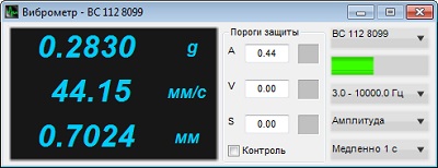
In order to evaluate the bottom level of the reproduced vibration acceleration and displacement, you can use the “Vibration meter” program.
The operation “Evaluation of vibration acceleration, vibration displacement and frequency response” should be conducted at the control point of the shaker table at zero load and at 25% load from the nominal value respectively.
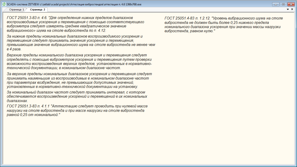
From the applicable standards, it follows that the vibration noise level at the shaker table should not exceed 25% from the bottom level of nominal acceleration range at zero load of the shaker table.
For the purpose of vibration noise measurements, enter the “Vibration meter” program, select the measuring channel, to which the reference vibration transducer is connected, set the band-pass filter range “3.0-10 000.0 Hz”, measurement method “Amplitude”, averaging time “1 second” (figure 2).

Figure 2. “Vibration meter” program
As the bottom limits of the reproduced acceleration and displacement ranges, we shall consider the values of acceleration and displacement, exceeding that of the vibrational noise at the shaker table more than in 4 times. For the purpose of the reproduced acceleration bottom level evaluation, it is necessary to obtain the readings of the “Vibration meter” program at full readiness for tests performance and multiply the readings by 4.
The top levels of the acceleration and displacement ranges are calculated by means of the program “AC voltmeter” by checking the possibility of the vibration and acceleration top levels (specified in standards and technical specifications) reproduction in the nominal frequency range. As the top limits of nominal acceleration and displacement ranges, we shall consider the smallest of the reproduced values in the nominal frequency range at the excitation parameters not exceeding those specified in standards and technical documentation for the shaker.
By nominal frequency range, we mean the interval, allowing reproduction of acceleration and displacement in their corresponding nominal ranges.
The top limits of vibration acceleration and vibration displacement nominal range are calculated by means of the program “Signals generator”. In the program, it is necessary to set the minimum frequency value from the nominal frequency range (specified in the technical documentation for the shaker), set the corresponding output signal level for the upper acceleration and displacement limit at this frequency, set zero offset for the constant component. Based on the readings of the “Vibration meter” program, find the RMS values of the reproduced upper limit of acceleration and displacement. In a similar way, it is possible to calculate upper limits of the reproduced displacement and acceleration values for each frequency of the nominal frequency range, specified in the technical documentation of the shaker.
See also:
- Shaker calibration system
- Test-run of the shaker system
- Evaluation of vibration acceleration and frequency non-uniformity
- Evaluation of acceleration and/ or displacement harmonics ratio
- Calculation of lateral components ratio
- Calculation of distribution non-uniformity ratio
- Calculation of trunnion resonance frequency and the first resonance frequency of the system
- Evaluation of the shaker table vibration noise level
- Evaluation of the tolerance limit for maintenance of the acceleration and/ or displacement level at the control point
- Evaluation of the tolerance limits for reproduction of acceleration and displacement level at the control point


