Signal Filtration

Signal Filtration is used for filtering signals coming to the input channels of spectrum analyzers, strain-gauge stations, and seismic stations, for further processing by ZETLAB programs. Signal Filtration can also be used for processing virtual channels created by such programs as Vibration Meter, Strain-Gauge Sensor, etc. Signal Filtration operates with signals both in real time and with reproduced of recorded signals.

During various tests, measurements, diagnostics, and voice recognition carried out amid interferences, one faces the problem of accurate evaluation of some signal parameters, e.g. level, frequency, correlation with other signals. If the useful signal and interference are divided in the frequency area, the most popular method would be signal filtration.

Flow-chart

of “Signal filtration” program

It is possible to enable/ disable any of the flow-chart elements. The filters can be arranged sequentially.

Flow-chart-of-Signals-filtration-program-components

*PBF – pass-band filter, SBF* – stop-band filter

Interface

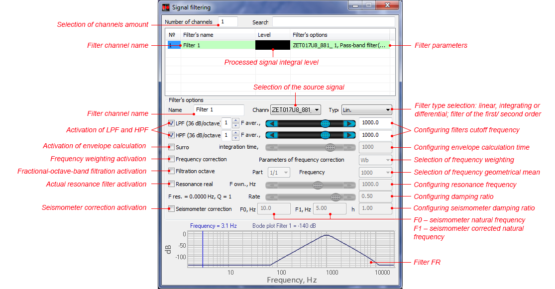
of “Signal filtration” program

Signal filtration program interface

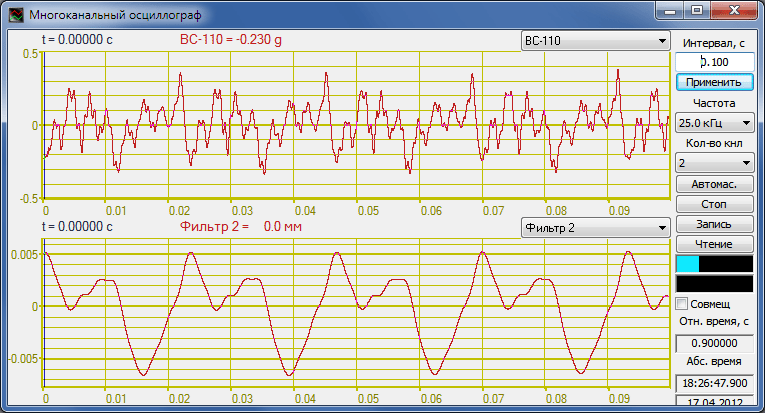
It is possible to view the results of filters operation from “Signal filtration” program using the “Multichannel oscilloscope” program. The upper diagram shows the time realization of the source signal, the bottom diagram shows the result of double integer function implementation and HPF of the Signal filtration program. The below example shows the accelerometer signal processing (the accelerometer is attached to the casing of the controlled device). Double integer function is used is implemented in order to turn acceleration signal into displacement signal, HPF is used to compensate for the drift of the received signal’s constant component.

multi-channel oscilloscope: signal filtration function

The filtration program creates additional virtual channels that are used for signal processing. All the signals – both real and virtual – have inner synchronization, allowing to process them simultaneously, for instance, with the program “Mutual spectral analysis”. The source signals for filtration remain unchanged. All the programs from the scope of ZETLab software package allow to process the real signals and the filtered virtual signals simultaneously.

Selection of the channels number for filtration.

The program allows to conduct filtration by several channels simultaneously. This function is available both for identical and different measuring channels, including the virtual channels.

Choosing the filter type

Differentiation and integration of the signals are widely used for vibration and acoustics studies. Most of the transducers used in vibration studies are represented by piezoelectric accelerometers, i.e. the sensors produce a signal, that is proportional to the acceleration value. A lot of controlled vibrational parameters of various mechanisms are set depending on particular acceleration level. For balancing of the rotational mechanisms, it is necessary to know the value of vibration displacement at the point of vibration transducer mounting. In order to obtain vibration velocity signal from vibration acceleration value, it is necessary to obtain first-order integer value of the signal. To get the vibration displacement value, it is necessary to double-integer the vibration acceleration value. In a similar way, it is also possible to obtain displacement velocity and acceleration signal from the linear displacement sensor using the signal differentiation function.

Implementation of integrating filters allows to use the analyzer as a high-precision vibration meter.

Signal differentiation is also very useful for the purposes of various systems vibration and acoustic monitoring. Among the key monitoring parameters, one should mention the process trend, i.e. long-term change of the controlled signal level in the time domain (e.g., integral vibration level or noise level). To control the change of the signal, it is possible to perform differentiation of the signal and to control the level of its derivative, i.e. the signal change degree.

In the case, if the input signal is represented by vibration acceleration signal (i.e. the measuring unit is “g” or “m/s2”), then, upon integration of the signal, the measurement unit for the output channel value will be vibration displacement – “m”. In the case of double integration of vibration acceleration signal the measuring unit of the output channel value will be vibration displacement – “m”. If the reference value “dB” of the input channel has been selected based on the ISO system requirements, then the ISO instructions should also be used for the output channels reference values of both integer and double integer functions. If the dB reference values have been selected based on GOST requirements, then the output channels reference values should be also assigned based on GOST system. Otherwise, it is necessary to add to the input channel measurement unit: “*c” for integer, “*c2” for double integer, “/c” for differentiation, “/c2” for double differentiation. In this case, the calculation reference value “dB” is not to be changed.

The Linear filter does not perform any operations.

Functions

of “Signal filtration” program

The program has an integrated control and automation module from the scope of ZETLab Studio, which makes it easy for the user to establish software measurement systems of his own design.

Frequency response and amplitude response characteristics of the filters can be obtained using the programs “Frequency response measurement” and “Lin. phase – frequency response measurement”.

“Aritmometer” program also enables implementation of the band-stop filter.