Bandpass filters
Signal filtration program
It is possible to use HPF and LPF for each channel of the signal filtration program. These filters are implemented as Butterworth filters of 2, 4, 6, 8 or 10 order with unlimited pulse response characteristics. The order of the filters depends on the ratio of the cut-off frequency to the sampling frequency of the filtered channel: the higher is the ratio, the higher is the order of the filter.
The following filter types are available in the program Signal filtration:
- LPF (low-pass filter) – passes the frequencies below Fcutoff,
- HPF (high-pass filter) – passes the frequencies over Fcutoff,
- Pass-band filter – passes the frequencies in the set band,
- Stop-band filter – stops the frequencies outside of the set band.
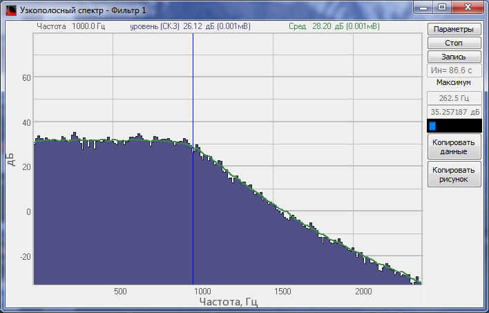

The cut-off frequencies of the filters are set in “Hz” at the level -3 dB. It is possible to evaluate the filter discrimination level by using the cascade filtration. The figures below show “white noise” signal spectrum, which has been processed by bandpass filters with the cutoff frequencies 500 Hz and 5000 Hz at different stages: without the processing, after a single iteration, after two iterations, after three iterations.
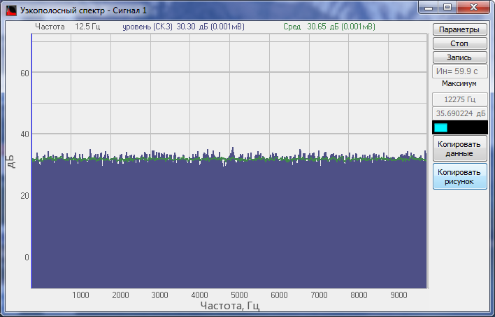
Source signal spectrum (white noise)
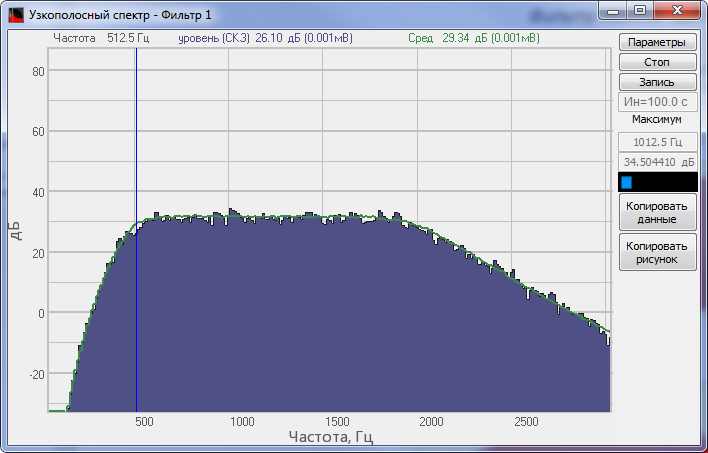
Pass-band filter 500…2000 Hz
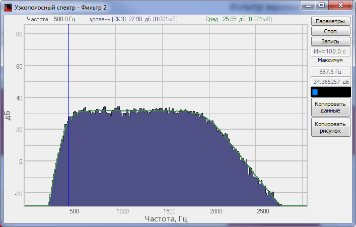
Pass-band filter 500…2000 Hz, two iterations
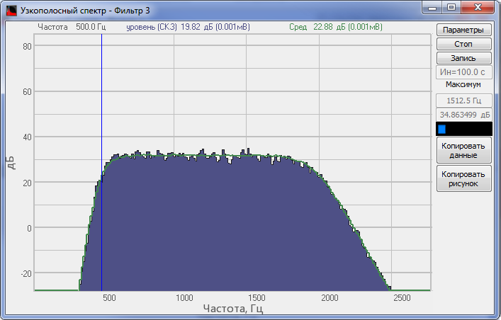
Pass-band filter 500…2000 Hz, three iterations
The cascade filtration is implemented in the following way: several channels are created in the program Signals filtration:
- 1-st channel of the program: the filter is applied to the source signal,
- 2-nd channel of the program: the filter is applied to the processed signal, i.e. to the first channel of the program,
- 3-d channel of the program: the filter is applied to the processed signal, i.e. to the 2-nd channel of the program,
- and so on, this sequence of operations is performed as many times as required.
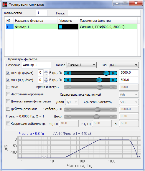
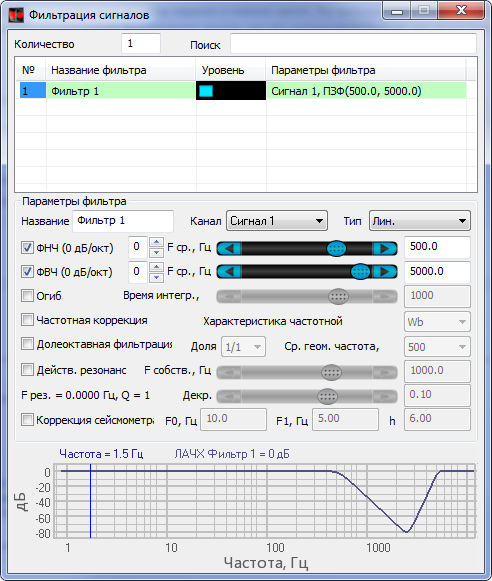
Pass-band filters and stop-band filters are created as a combination of HPF-s and LPF-s. Pass-band filter is implemented as a combination of LPF and HPF with cutoff frequencies FcutoffLPF > FcutoffHPF. In the case, if the cutoff frequency of LPF is less than that of HPF (FcutoffLPF < FcutoffHPF), then the stop-band filter is obtained. The figures below show examples of pass-band filters and stop-band filters with the cutoff frequencies 500 Hz and 5000 Hz.
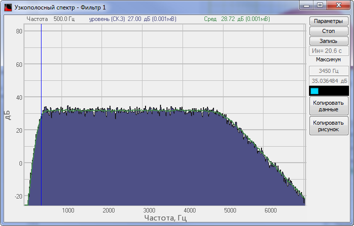
Pass-band filter FcutoffHPF = 500 Hz; FcutoffLPF = 5000 Hz
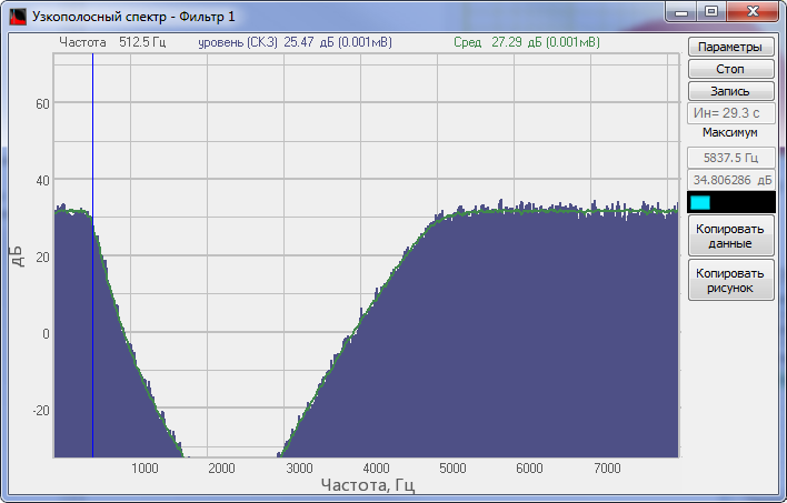
Stop-band filter FcutoffLPF = 500 Hz; FcutoffHPF = 5000 Hz
The figures below show an example of Signals filtration program configuration for implementation of pass-band filters and stop-band filters: