Charge amplifier ZET 440


Charge amplifier ZET 440 for piezoelectric detectors is intended for:
- amplification and conversion of output signals of primary piezoelectric transducers with charge output;
- amplification and conversion of output signals of primary transducers with the IEPE type in-built electronics to voltage;
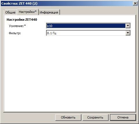
- gain ratios: 1, 10, 100;
- LPF: 0.1, 1, 10 Hz
POR (price on request)
The ZET 440 preamplifier is used in vibration detector calibration system to connect AP10 reference acceleration meter to the ZET 017 FFT spectrum analyzer. In combination with vibration measuring converters, the amplifiers can be used in technical diagnostics and monitoring systems implemented in various industries for measuring vibration and shock accelerations as well as in laboratory and scientific studies.
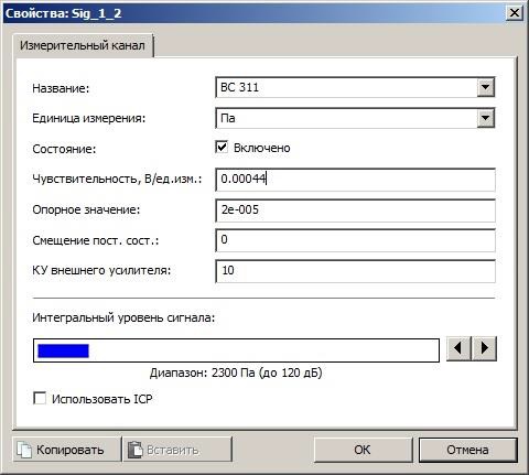
The ZET 440 amplifier allows to connect acceleration meters with charge output or of IEPE standard to FFT spectrum analyzers as well as to ADC and DAC converters. It also allows to connect the BC 311 sonic detectors to the ZET 017 FFT spectrum analyzer.
Specifications
of the ZET 440 Charge Amplifiers
| Technical Specifications | |||
|---|---|---|---|
| Number of channels | 1 | ||
| “Charge” Input | |||
| Socket type | BNC | ||
| Charge gain | 1 mV/pC | 10 mV/pC | 100 mV/pC |
| Maximum input charge (peak) at GR=1, min. | 104 pC | ||
| Operating frequency band with -3 dB attenuation at the boundaries and non-linear distortion coefficient below 10%: | |||
| within the output voltages range not more than 2.5 V (peak) | 0.1 ~ 100 000 Hz | ||
| within the output voltages range not more than 5 V (peak) | 0.1 ~ 50 000 Hz | ||
| within the output voltages range not more than 10 V (peak) | 0.2 ~ 30 000 Hz | ||
| RMS of noise reduced to the input in “Charge” mode with sensor capacity 1 nF within 0.1 ~ 20 kHz frequency band (at gain 1 mV/pC), max. | 0.04 pC | ||
| “IEPE” Input | |||
| Socket type | BNC | ||
| Voltage gain | 1 | 10 | 100 |
| Maximum input voltage (peak) at GR=1, min. | 10 V | ||
| Operating frequency band with -3 dB attenuation at the boundaries and non-linear distortion coefficient below 10%: | |||
| within the output voltages range not more than 2.5 V (peak) | 0.1 ~ 100 000 Hz | ||
| within the output voltages range not more than 5 V (peak) | 0.1 ~ 50 000 Hz | ||
| within the output voltages range not more than 10 V (peak) | 0.2 ~ 30 000 Hz | ||
| RMS of noise reduced to the input in “IEPE” mode within 0.1 ~ 30 kHz frequency band, max. | 20 µV | ||
| General Specifications | |||
| Main permissible relative accuracy limits for setting the gain at 1 kHz frequency at normal conditions | ±0.6 % | ±0.6 % | ±1.2 % |
| Additional permissible accuracy limits for setting the gain within 0 ~ 40°C temperature range | 0.5 % | ||
| Amplitude-frequency characteristics unevenness within 3 to 20,000 Hz band | ±0.5 % | ||
| Cutoff frequencies of the in-built LPFs with at least 40 dB/decade amplitude-frequency characteristics and -3 dB attenuation | 0.1 Hz | 1 Hz | 10 Hz |
| Output socket type | BNC | ||
| Maximum output voltage (peak), min. | ±10 V | ||
| Output resistance (for load current not more than 10 mA), max. | 50 Ohm | ||
| Feed mode of sensors with IEPE type in-built amplifier: voltage current |
27 ± 3 V 3 ± 1 mA |
||
| Galvanic separation | |||
| resistance, min. | 0.3 MOhm | ||
| permissible in-phase voltage, max. | 260 V | ||
| Operating mode setup duration, max. | 20 sec | ||
| Continuous operation time, max. | 8 h | ||
| External DC power supply | 12±1 V | ||
| Consumed current, max. | 230 mA | ||
Flow Diagram
of the ZET 440 Charge Amplifiers

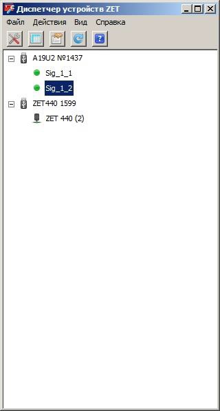
The charge output vibration sensors are connected to “Charge” input, while IEPE standard acceleration meters are connected to IEPE input. Signal from the sensor passes through the high-pass filter with the cut-off frequency of 0.1, 1.0, or 10.0 Hz, then through the amplifier with 1, 10, or 100 gain, and then through the pseudo-galvanic separation, the signal is fed to the ZET 440 output. The input of the amplifier (“Charge” or “IEPE”) to which the vibration sensor is connected to, is determined automatically. Gain (sensitivity, amplifier conversion coefficient) and high-pass filter cut-off frequencies are set in the ZETLAB Device Manager Software.