System selection and mounting
in the course of structural health monitoring system design
In order to select structural health monitoring system components (SHM), it is necessary to perform a number of procedures, which will help to choose the suitable digital sensors, their quantity, and mounting areas:
- Define the controlled parameters and then select the particular SHM subsystems enabling control in accordance with the set requirements.
- Find out information on the number of floors and foundation’s square of the controlled object using corresponding design documentation.
- Define the necessary amount of the digital sensors to be included in the structural health monitoring system using the information from the clause «System components and controlled parameters».
- Mark digital sensors location for each of the levels (floors) of the controlled object (building).
When choosing digital sensor’s location it is necessary to take into consideration further cable connection.
If the building has 7 or fewer floors, the sensors are to be installed at the bottom part (at level/floor, which is as close to the foundation as possible) and at the top part (at the level/floor in direct vicinity to the ceiling). In the case of high structures, it is also necessary to select several intermediate floors for the control purposes in accordance with the information specified in the clause «System components and controlled parameters».
Transducer, that are used in the Structural health monitoring systems (in particular, for the purpose of vibration measurement) should be able to detect low-level oscillation modes from the data with high noise interference, attributed to the response of the structure under research to the impact of vibration sources. The level of the specified impacts is normally very low. Ranges of structural response for some vibration sources are specied in ISO 4866:2010 “Mechanical vibration and shock — Vibration of fixed structures — Guidelines for the measurement of vibrations and evaluation of their effects on structures”.
| Vibration source | Frequency range, Hz | Amplitude range, μm | Velocity range, mm/s | Acceleration range, m/s2 |
Time characterisitc* |
| Traffic road, rail, ground-borne |
1 – 80 | 1 – 200 | 0,2 – 50 | 0,02 – 1 | C/T |
| Blasting vibration ground-borne |
1 – 300 | 100 – 2500 | 0,2 – 50 | 0,02 – 50 | T |
| Pile driving ground-borne |
1 – 100 | 10 – 50 | 0,2 – 50 | 0,02 – 2 | T |
| Outside machinery ground-borne |
1 – 300 | 10 – 1000 | 0,2 – 50 | 0,02 – 1 | C/T |
*C – Continuous
T – Transient
In compliance with the provisions of ISO 4866:2010:
- the specified ranges represent the maximal possible values, however, these values may still occur;
- the specified frequency ranges correspond to dynamic response of structures and structural elements for a particular impact type (the information quoted is for reference purposes only);
- vibration values with the specified ranges may require attention. There are no standards which would encompass all types of structures, as well as impact duration and impact environment. However, many national building codes associate the threshold of visible (or otherwise detected) effects with peak accelerations of particles in the foundation of the structure (in the case if the peak accelerations exceed the level of several millimeters per second). There is a high possibility of some defects occurrence in the case of peak particles velocity of several hundred mm/s. Vibration levels below the human perception threshold may require attention only in the case of high-precision manufacturing processes.
Based on the information available in the specified document, the measurement units of SHM subsystem should enable detection of vibration impacts of both high and low levels, as well as to have low noise spectral density.
Accelerometers ZET 7152-N and velocimeters ZET 7156 comply with the relevant specifications. Recommendations concerning installation of the transducers on the controlled structures are as follows:
- Velocimeters ZET 7156 should be mounted on concrete foundations as close to the bearing structures/walls of the building as possible.
- It is recommended to install accelerometers ZET 7152-N at low levels of the structures to be controlled.
For the purpose of the best possible positioning of the accelerometers used for fundamental tone frequency control at the stage of design and survey work one can use «Mobile measuring system: natural oscillation frequency and decrement measurements».
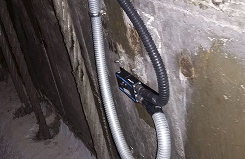
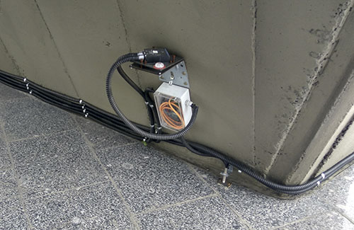
ZET 7154 inclinometers (tilt meters) are to be mounted on elements (intermediate slabs, bearing walls, ceiling bearing structures, bearing elements, etc) that are subject to tilt control monitoring.
ZET 7110-DS strain-gauge sensors are mounted on structural elements (intermediate slabs, bearing walls, ceiling bearing structures, bearing elements, etc) for the deformation control purposes.
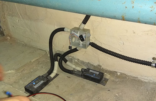
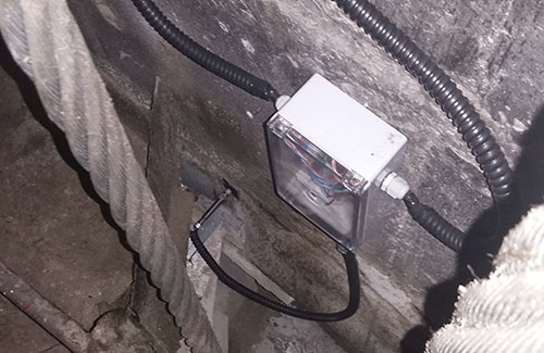
ZET 7140-S eddy current sensors and ZET 7180-I digital modules together with RF603 laser sensors are used for structural elements relative displacement control. These measuring modules should be installed in the areas where the occurrence of such displacement processes is most likely.
Upon completion of digital sensors installation, it is necessary to choose data acquisition nodes locations as well as the necessary amount of interface converters for each of the electrical cabinets.
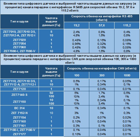
When choosing the locations for data acquisition nodes cabinets it is necessary to make the measuring lines as short as possible. While calculating the total amount of the converters to be used, one should take into consideration the limitations concerning the cable line length specified in the clause «Measuring lines: design process», as well as the table of data transfer channel load.
As the locations of data acquisition nodes cabinets are known, it is necessary to design connecting cables routes in the object (building) scheme.
The modules placed inside of data acquisition nodes cabinets (interface converters, power supply sources and so on) are mounted on DIN-rails.
Each interface converter should be connected to industrial PC of the data acquisition node or (in the case if there are no PC-s in the structure of data acquisition nodes) to the SHM system server – for that purpose, Ethernet converters are used (the Ethernet converters have a corresponding amount of ports).
In the case if the Ethernet data transfer cable line length (from data acquisition nodes panels to the server) is less than 100 meters, it is possible to use Class 5 twisted pair. In the case of implementing longer cable lines, there should be used a fiber-optic cable with optical media-converters at both ends of the cable.
