
Automated (computer-aided) test stands
It is necessary to carry out complete, continuous technical specifications supervising of produced devices to improve quality, reliability and the competitiveness of the manufactured products. It’s possible only with testing process automation and creation of specialized systems (stands).
Automated testing stands imitate tested component functioning within the ready-made product at the manufacturer stated modes. Testing of the component with automatic reading of all the parameters is aimed at the production quality control.
Purpose of the test stands
- products quality improving,
- electricity consumption shortage,
- reduction of the human factor influence, improvement of the personnel working conditions at the cost of test process automatization and use of the modern equipment, which meets ultimate technical, ergonomic and sanitation requirements.
Application fields of the automated test stands
It is possible to identify three main stages in the life cycle of a machine or equipment in terms of the diagnostics:
- designing and research of the prototypes;
- manufacturing or repairing of factory products, its installation and setup at the operating area;
- condition monitoring within the operational period between repairs.
Every single stage is accompanied by multiple tests, which, frequently, are carried out according to the same procedure. Once you implement the testing algorithm in the computer appliance, you can automatize the testing process. It will improve not only the productivity, because in the automatic mode the measuring is carried out significantly quicker, but also the accuracy, because the virtual devices allow to carry out the measurements through several channels at a time, guaranteeing the signals uniformity at the relative measurements and tests, which are carried out by the method of comparison with the example. Besides, mathematical treatment of the results can also be carried out automatically because by the end of the testing you can see the values of the measured parameters and their deflections from the nominal ones on a screen (and in the report!).
Stands design
Automated stands designed for acceptance tests and other types of testing is a computer appliance. Virtual equipment implements the management of attached devices during testing. So that allows to completely automatize the process, as far as the operator don’t have to commute the measuring channels (it does the commutation unit), to measure power parameters (the programing power source is used), to set the value of the generator (DAC output is manipulated automatically too), to take the readings (the changing results register in the testing log, measure setups and changing periods are picked up according with testing conditions), to perform calculations (SCADA ZETView system has powerful mathematical tool).
Hardware component
Hardware component of the stand is built around the spectrum analyzer and the commutation unit, and it can also include other devices. The set of devices are picked up according to the stand functionality, device type that means its technical parameters according to required precision characteristics.
- Spectrum analyzer implements assigning and measuring functionsThe analog signals from the tested device come in to inputs of ADC. Measurement of the signals parameters is carried out by the virtual devices according to method requirements. The testing signal from the DAC output comes in to the input of the testing device. That signal is of sinusoidal kind, pulse-shaped, saw-toothed, dc signal etc. Digital input/output can be used for receiving/transferring of the digital signals.
- Amplifiers are used for the signal amplification and galvanic isolationIf necessary, the stand can include signal pre-amplifier with galvanic isolation and without it.
- Commutation unit is used for switching of measuring and testing circuitrySwitching of circuitries allows to feed test signals to all the inputs of a testing device in consecutive order and, vice versa, to connect the measuring circuitries to input channels of the spectrum analyzer. Thus, the number of channels of ADC/DAC stand is determined by the number of simultaneously measuring/testing signals. The using of the commutation unit for software switching of the channels frees an operator from channels switching necessity.
- Power sources are used for providing the power supply for the testing device or the stand elementsAutomated stands for substandard devices test often include the programmable power sources, because tested devices could require different power parameters for different tested parameters.
- Multimeters are used for a precision measuringBy testing spectrum analyzers and others devices requiring utilizing more precise meter, the stand can include the precision multimeter like Agilent kind, for instance.
- ADC/DAC cards are used for the parameters monitoringCarrying out the values monitoring, which don’t require high precision, instead of spectrum analyzers ADC/DAC cards can be used, this will sufficiently reduce the cost of a stand.
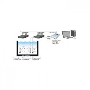
- Primary transducers are used for nomenclatural measuring parameters extensionFor measuring such parameters as temperature, pressure, acceleration, intensity and others the stands can include various sensors of thermocouple, thermal resistance, strain gage, accelerometers, motion etc. Automated sensors test stands by means of the comparison method include primary transducers, which are used as the exemplary ones. Distinctive feature of such sensors is high precision and more dynamic range.
- Testing equipment is used for testingTo provide required conditions for testing the automated stands can carry out managing of various devices and mechanisms such as vibration stands, rotary units, tension testing machines, environmental cameras etc. In the stand operation can be utilized existed equipment of the company, or the stand can include all the necessary devices.
- Specialized developments are used for additional devicesThe stand can include not only the standard devices form the native and foreign manufacturers, but also specialized ones performing functions designated by testing methods requirements. It can be the transduction cards (for transduction encoded information), various devices simulation (for signals imitation during the testing of the mechanisms constituent parts) etc.
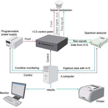
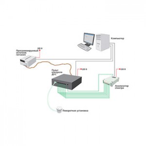
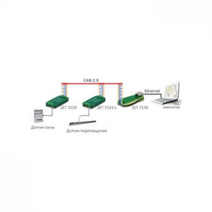
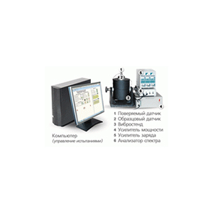
Figure 1 — Block diagram of the automated test desk hardware “Spin-rate meter calibration”
Several hardware devices can be combined within the single casing. Figure 1 shows the example of the automated stand for the angular velocity sensors calibration (description of the software component is put out in the last chapter of this article), including the spectrum analyzer, programmable power source, rotating mechanism and control panel with commutation unit and the signal amplifier.
Software component
Software component of the stand is implemented in the SCADA ZETView system. The testing algorithm builds in type of block diagram according with the testing method.
Flexibility
At the designing stage of the project the necessary flexibility degree is took into consideration. The stand can be specialized for testing the devices of a certain type, for instance, during the total outgoing monitoring and has only one button “START”, or it can be used with various devices and has multiple manipulating elements.
Specialized stands
The specialized stands are designed for testing of a certain device type when the operator enters a device number and starts the test.
In such projects can be specified the option of test type or testing conditions (Figure 2), according to which the conditions of measuring will change, for instance, the list of testing parameters, nominal value of parameters, margins of errors etc.
Figure 2 — choosing the test type and testing conditions
Also in specialized stands the possibility of the selection check is usually specified. In that case an operator chooses the test type:
- All parameters check (total control)
- Some of the parameters check (selection check)
- One of the parameter check
The special feature of the specialized stands is that the operator doesn’t set the checking parameters directly (the values of supplying voltages, nominal value of the parameter etc.) because all this data is already in the project. The operator chooses the check type; test conditions etc. and all the parameters are set up automatically, whereupon the algorithm, corresponding for the chosen test, is starting up.
The example of the specialized stand is “Calibration of the angular velocity sensors”
Multipurpose stands
The multipurpose stands allow to carry out testing of various devices types with the similar parameters. The operator chooses the device type from the list, and the test parameters such as the values of the testing signals, frequency range, dynamic range, the list of checking parameters, the nominal values of the parameters, margins of errors etc. change according to the chosen type.
Those stands, as a rule, have more complicated interface, giving the operator the opportunity to change the program setups.
The examples of the multipurpose stands are “Spectrum analyzer verification”, “Vibration transducers verification”.
Multifunctional stands
The multifunctional stands allow to carry out tests in various modes such as verification, calibration, debugging etc. For instance, in the check mode the device parameters are determined and the conclusion, regarding its correspondence to the normative documentation requirements, is made, but in the calibration mode the corrections are inserted to the calibration table.
The debugging mode allows the operator to carry out measurements under the conditions, which are different from the ones stated in the test methodology, for instance, to determine the correction coefficients for the device operation at the high temperature conditions.
The multifunctional stands allow to carry out not only the periodic device tests, but also its testing and researching the influences of various parameters to the device readings.
The example of the multifunctional stands is “The electric circuit monitoring device”.
Interface
The external view of the program is set up according to the company standards. The programs can take small portion of the screen or have several pages, have the additional set up windows and configuration files (for saving different accounts).
Presenting the results
The measuring results, besides the standard presentation in numeral and diagram formats, can be presented in tabular format, as light indicators and indication symbols:
![]()
![]()
![]()
Messages for the operator
The instructional messages (for instance, connect the plug to the input), questions (“Was the indication observed on the device panel”) with the answer options can be displayed on a screen. Also light and sound alarms can be implemented in the project.
Figures
The projects can contain images, for example, connection schemes, explanatory illustrations (Figure 3, Figure 4 are the position “1” and “0” at the torque measurement of the tested device). The illustration can vary according to the test type and other parameters. Also the illustrations can be dynamic and to demonstrate, for example, the order of the machinery components connection.
 Figure 3 — locking in position “1” |
 Figure 4 — locking in position “0” |
Creating the reports
One of the obvious automated stands advantages is the preserving of the measuring results as the test record sheets of the given form. The record sheets can be created automatically by the end of the measuring or by the operator pushing the button. The directory for reports preservation can be selected automatically by date, device type and test results.
The reports can be created in .txt, .dtn, .doc, .xls formats. The types of transferring data can be of numerical values, digital scope, text format, diagrams and date. It is also possible to present the results in the form of lines “the testing sample meet the requirements of TU ХХХХ-ХХХ—ХХХХХХХХ—ХХХХ” or “According to the test results the introduced sample is considered as unusable” etc.
Testing report can be inscribed into the form with the company details.
Making the alteration
As far as the software component of the automated stands usually performs in the ZETView visual programming environment, making the alteration doesn’t take too much time and special requirement of the personnel level of proficiency. The testing algorithms bring about in the flowchart format. The AC voltage measuring algorithm and comparisons of the obtained value with admissions are introduced in Figure 5. By changing the admission values, it’s enough to indicate the new value in the “Const” component setups (“Value” option). It’s easy to find this component, it has the pictogram with “Const” inscription. The setup window is situated at the right side of a screen.
Figure 5 — the layout of AC voltage changing and comparison of obtained value with admissions (engineering interface)
The accomplished project is compiled in the form of executable file, and the initial project is kept on a disc, which is a part of the stand.
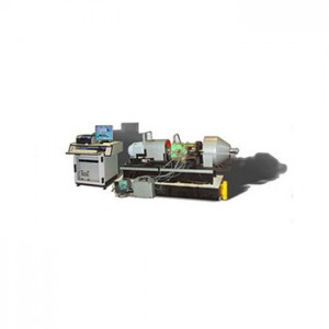
Tension testing machine automatization
Vibration sensor verification
Conclusion
The automated test stands find many fields of application:
Various types of tests:
- factory acceptance,
- periodical,
- typical.
Various test methods:
- certification,
- verification,
- calibration,
- precision characteristics monitoring.
Multipurposness
The stands are designed around multipurpose devices, which allow to use the same appliance for various testing. One stand can have several programs for certain device type testing. Thus, the multifunctional “test centre” can be situated at an operational area.
Flexibility
At the designing stage the “level of freedom”, that should be given to the operator, is taken into account. The projects can have parameters windows with the modes switchers, the lists of parameters values and the input fields. It is possible to review data during the setup (calibration tables, configuration files). The stands can have the system of remote setting system.
Intuitive interface
As far as the software component of the stand is designed for resolving specific tasks, the program interface is especially handy and useful to work with the stand. The active terminology, colour codes, data formats and reports forms completely correspond with the company standards.
The maintainability simplicity
Creating of projects in visual programming environment allows to make the alterations by an ordinary user, without programming skills, fast and easy. The hardware component is designed on the basis of multipurpose devices and provides the easiness of the failure device replacement. Every stand is stocked with the engineering documentation regarding the hardware component of the stand, and the manuals for the programmer (the project design description), the operator (the project operation) and the user manuals (the terms of use and setup methodology).