
IEPE TECHNOLOGY
ICP/ IEPE Technology
IEPE technology (Integrated Circuit-Piezoelectric) is developed by PCB Piezotronics company and used for manufacturing vibration, shock, tension, power and pressure sensors.
What Is IEPE Sensor
ICP sensor is a device for measuring dynamic pressure, power, deformation, or acceleration. The sensor contains a sensitive cell made of piezoelectric material which converts mechanical load into electric signal and microelectronic circuit to amplify the signal and transmit it to external devices. Since the piezoelectric cells generate electric signal only under the effect of dynamic forces, the accelerometers cannot measure mechanical fluctuations with frequencies reaching 0 Hz. The used preamplifier determines electric signal leakage speed generated by piezoelectric cells of an accelerometer.
Power supply of built-in charge preamplifier is performed via a two-wire circuit.
Main advantages:
- wide frequency range;
- linear amplitude characteristic in wide dynamic range;
- possibility to receive a signal proportional to vibration speed and vibration relocation by using integrators connected to accelerometer output. Application of electronic integrator is identical to activation of low-frequency filters which causes attenuation of high-frequency vibration components;
- ability to operate in severe ambient conditions (temperature, humidity, radiation and magnetic fields);
- high mechanical reliability and durability at the expense of moving parts in the sensor;
- high vibration resistance and shock resistance;
- no need in power supply because the IEPE sensor is a generator-type sensor;
- compact structure and a large ratio of sensitivity to mass.
Connection
For correct operation, all IEPE sensors require DC power supply. Typical connection system includes IEPE sensor, typically a two-wire DC power cable and power supply as shown in Figure 1.

Figure 1 Standard IEPE sensor connection diagram
1 — from 18 to 30 VDC; 2 – current stabilization diode; 3 — coupling capacitor (standard value of 22 mF, >35 VDC); 4 — filter resistance; 5 — measuring instrument; 6 — 2-contact connector; 7 — amplifier; 8 — piezoelectric crystal; 9 — Faraday cage; 10 — body sensor.
Signal converter consists of a stabilized DC power supply 18…30 V (battery or mains), current stabilization diode (or equivalent DC circuit) and the capacitor for site isolation.
The current stabilization device above is used instead of resistor for several reasons. Very high dynamic resistance of diode provides gain of source follower, which is very near to 1 and does not depend on input voltage value. In addition, the diode can be replaced to provide large current values for DC connections, as shown in Figure 2 (the correct diode orientation in the diagram is critical for correct operation). Except for special models, standard ICP/ IEPE sensors require minimum 2 mA for correct operation.
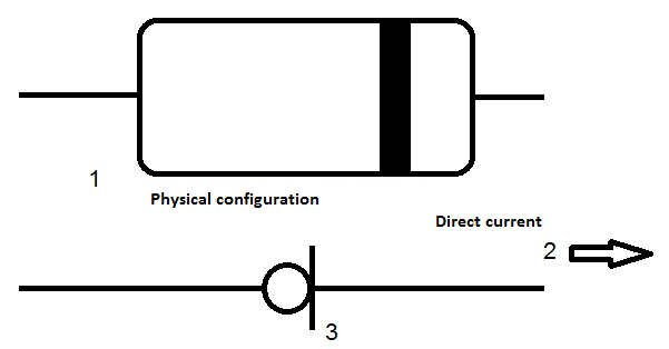
Figure. 2 DC diode
1 — physical configuration; 2 — DC current flow direction; 3 — equivalent electric circuit.
Typical limit value for such type of diode is maximum 4 mA, but several diodes can be connected at the same time for high current levels. Instead of diodes, all signal converters with mains power must use DC circuits (current up to 20 mA), especially when using long distance cables.
Data signal is isolated in output stage of signal converter. The capacitor with 10-30 mF capacitance together with a resistor shift the sensor displacement voltage removal signal level. It results in operation in AC mode without drift.
Common names for the technique of built-in impedance conversion in piezoelectric transducers, for a few of the largest manufacturers. Other manufacturers use other names. ICP/IEPE is currently the most common name used by analyzer manufacturers, although IEPE is starting to take over.
| Manufacturer | Brand name |
|---|---|
| Brüel & Kjær | Deltatron™ |
| Dytran Instruments | LIVM™ |
| Endevco | Isotron™ |
| KistlerInstrument Corp. | Piezotron® |
| PCB Piezotronics Inc. | ICP® |