
Piezoelectric Accelerometers
A piezoelectric accelerometer is a vibration sensor supplying AC electric signal.
The energy conservation law prescribes that it is impossible to obtain energy on any device output (including accelerometer) without energy on input of this device. Static force applied to accelerometer piezoelements is not accompanied by energy on its input. Therefore, the piezoelectric accelerometer does not provide DC signal at all. The simplest and most widely used check method of accelerometers, kits and systems containing them is based on a base source of mechanical fluctuations with precisely set parameters, i.e. calibrated vibration board.
Quality Requirements to the Studied or Tested Object Surface
One of the important conditions for preserving a high resonance frequency of fixed accelerometer and therefore its wide operating frequency range is the highest possible quality of the tested object surface (flat, smooth and clean) at and around the accelerometer mounting location. It should be noted that the contaminated surface must be thoroughly cleaned, for instance with appropriate industrial solvent, for example, with acetone.
Transverse Sensitivity
The piezoelectric accelerometers are sensitive not only to mechanical fluctuations in the direction of their principal (longitudinal) axis, but also to some extent to fluctuations at the perpendicular plane. The transverse sensitivity is expressed in percent of the sensitivity value in the direction of the major axis. An accelerometer with zero transverse sensitivity would be considered to be ideal. But the small inaccuracies of piezoelements and metal parts, actually make it impossible to create ideal accelerometers insensitive to transverse fluctuations at all. During production of accelerometers, great attention is paid to pure and unified piezoelectric materials and accuracy of processing, adjustment and assembly of separate parts. Thus, the transverse sensitivity of accelerometers in reliable state and solidly fixed on the flat and clean surface at 30 Hz frequency does not exceed 4% of their nominal sensitivity in the direction of the principal axis.
The transverse sensitivity of reliably fixed accelerometers does not exceed 10% of their nominal sensitivity in the direction of the major axis in entire frequency range with upper threshold equal to value of respective resonance frequency calculated on 6. At the frequencies close to (multiplication coefficient approx. 1/3) the resonance frequency of the fixed accelerometer, it is actually impossible to define exact transverse sensitivity resonance frequency value. It depends on transverse resonance of the accelerometer located in a respective area.
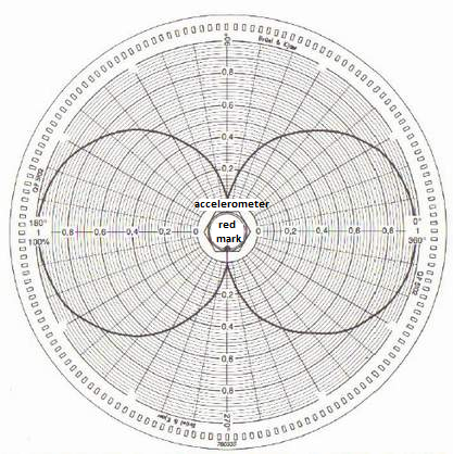
Diagram depicting the accelerometer transverse sensitivity related to different directions.
Mounting Points of Accelerometers
Locations of accelerometer mounting points are often directly connected to the measured objects. It should be emphasized that when choosing the mounting points, it’s necessary to align fixed accelerometer maximum sensitivity axis (major axis) to the direction corresponding to conditions of the research. It is reasonable to direct the body of the fixed accelerometer in such a way so that to ensure red mark matching the direction of transverse fluctuations having maximum amplitudes. Following this instruction contributes to significant reduction of the influence of transverse fluctuations of the studied or tested object.
Accelerometer mounting points must be chosen with consideration of achieving the shortest possible and well-defined paths of mechanical fluctuations spreading from their sources to the vibration sensors. Between the mechanical fluctuations sources and accelerometers mounting points only rigid elements must be located, while resilient and/or damping cells (springs, gaskets etc.) are not allowed. For example, during research of mechanical fluctuations of rotational equipment, bearing cases are optimal in terms of accelerometer or accelerometers mounting.
Mechanical fluctuations research often requires information relating to only one of the principal axes (vertical or horizontal) of the equipment. But the triaxial accelerometer allows to simultaneously study the mechanical fluctuations in directions of three mutually perpendicular axes.
Accelerometer Transfer Characteristics
During research of short-term (transition, impulse etc.) mechanical fluctuations and mechanical shocks, it is necessary to pay special attention to linearity of used vibrometric equipment, as any non-linearity of any element causes wave shape distortion of signals reflecting researched processes. The piezoelectric accelerometers are highly linear vibration sensors contributing to undistorted processing of different kinds of short-term mechanical fluctuations and shocks. In the systems containing these accelerometers, a probable cause of distortions and other difficulties are represented by simultaneously used preamplifiers and most often different integrators and/or filters. However, to ensure necessary precision, reliability, and reproducibility of results during researches of short-term mechanical fluctuations and mechanical shocks, it is reasonable to take into consideration phenomena and processes described below.
Constant Natural Fluctuation Frequency.
Constant natural fluctuation frequency is one of the basic parameters of accelerometers despite its very limited application in vibrometric practice. One of the constant natural fluctuation determination methods requires excitation of accelerometer suspended on connection cable of the accelerometer by a DC signal supplied to it by a corresponding generator through the 1 nF capacitor. Frequency of constant natural fluctuations is a frequency at which signal excitation voltage and current flowing through the accelerometer exactly match each other by phase. The approximate value of this frequency is defined with oscilloscope on the VDT screen of which the voltages at accelerometer outputs and the mentioned capacitors are displayed simultaneously, and the result is obtained after the 90° phase change of the mentioned stresses. During practical application of this system, excitation signal frequency is adjusted before forming on the VDT oscilloscope display of the Lissajous figure in form of a circumference corresponding to phase shift equal to 90°. Frequency of the constant natural fluctuations of accelerometer is then equal to adjustment frequency of the generator which supplies the excitation signal.
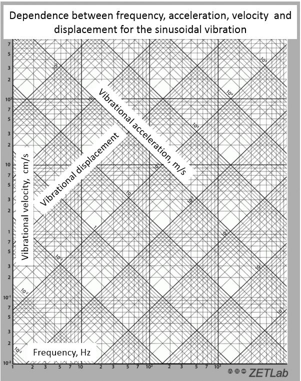
Nomogram for Recalculation of Different Mechanical Fluctuation Values
The nomogram below shows correlations between different quantities of mechanical fluctuations, i.e. frequency, relocation, rate, and harmonic mechanical fluctuations acceleration. Based on two values, this nomogram helps to define two remaining mechanical fluctuations. Click on the image to zoom.
Source: Theory and Operation Guide.
Piezoelectric accelerometers and preamplifiers. Brüel & Kjær.