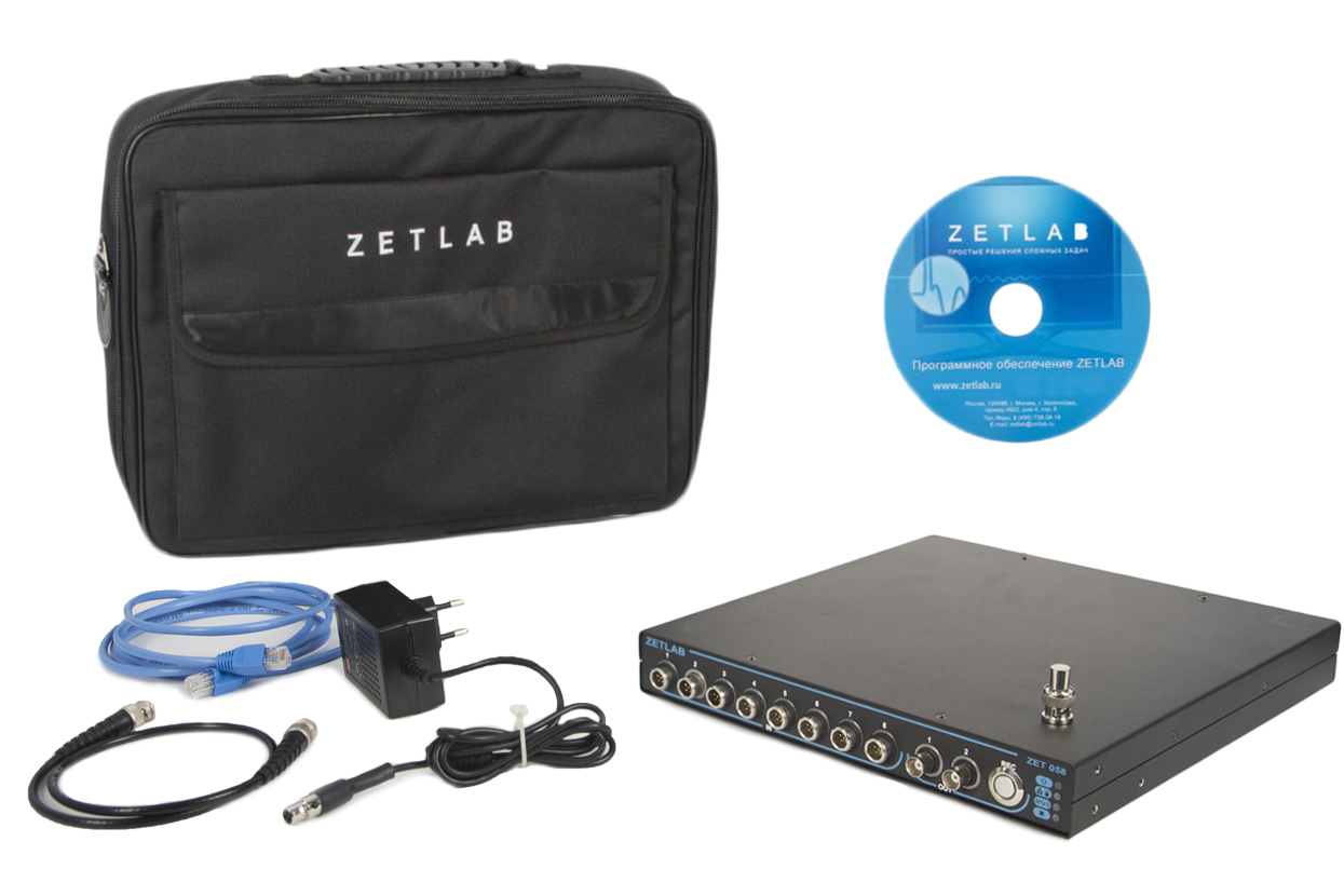
Strain gauge measurement system ZET 058


- The system supports connection of various strain gauge transducers and sensors with voltage output;
- AC/DC power supply of primary transducers;
- Parallel data processing by a large number of channels;
- User-friendly software.
POR (price on request)
Specifications
of Strain gauge measurement system ZET 058
| Technical specifications | |
|---|---|
| Analog output (ADC) | |
| Number of analog voltage outputs | 8 |
| ADC digit number | 24 |
| Frequency ranges of simultaneously analyzed signals | DC…2, DC…20, DC…200, DC…2 000, DC…20 000 Hz |
| Max. sampling frequency | 400 kHz |
| Max. input current at unitary amplification ratio | ±10 V |
| programmable amplification ratios | 1, 10, 100 |
| Range for in-phase signal | ±9,5 V |
| Integrated generator | 8 synchronous generators output voltage ±10 V output current 10 mA |
| Analog output (DAC) | |
| Number of analog outputs | 1 |
| Frequency range of the generated sinusoidal signal | 0,03… 20 000 Hz |
| Output impedance | 50 Ohm |
| Max. output current | 10 mA |
| DAC digit number | 16 |
| Max. output voltage value | ±10 V |
| Digital input/ output | |
| Digital input | 8 bit |
| Digital output | 8 bit |
| Digital input/ output logic type | TTL |
| Metrological specifications | |
| Analog input (ADC) | |
| Dynamic range | 130 dB |
| Identity of channels in the band-pass | 0,1 % |
| Cross-channel phase difference | 1° per 10 kHz |
| Noise spectral density in the band 30…20 000 Hz, no more with gain=100 with gain=10 with gain=1 |
15 nV/√Hz 40 nV/√Hz 350 nV/√Hz |
| Analog output (DAC) | |
| Limit of admissible relative error for frequency set-point for the range of 3…25 000 Hz | ±0,1 % |
| Limit of admissible relative error for frequency set-point for the range of 0,03…3 Hz | ±10 % |
| Admissible tolerance limits for output DC and AC voltage setpoint | ±(0,2 % + 2 mV) |
| Harmonic coefficient of the generated sinusoidal signal | 0,1 % |
| Strain-gauge measurement specifications | |
| Connect up sensors | full-bridge, half-bridge, quarter-bridge |
| Temperature drift of the internal measuring circuit when using a bridge or half-bridge sensor in the temperature range of 15 … 25 °C | <320 nV/(V°С) |
| Quarter-bridge resistance range | 30…1000 Ohm |
| Temperature drift of the internal measuring circuit when using a quarter-bridge sensor with sensor resistance (Rs)* in the temperature range of 15..25 °C | Rs=400 Ohm, <15 µV/(V°С) Rs=300 Ohm, <60 µV/(V°С) Rs=200 Ohm, <150 µV/(V°С) Rs=150 Ohm, <250 µV/(V°С) |
| Non-identical temperature drift of the internal measuring circuit when using a quarter-bridge sensor with a sensor resistance of 200 Ohm in the temperature range of 15..25 °C | ±50 µV/(V°С) |
| Full-bridge supply voltage | DC: 10..10000 mV AC (RMS): 10..7000 mV |
| Carrier frequency | DC…20 000 Hz |
| Sensor supply current | to 10 mA |
| Operational specifications | |
| Dimensions | 280 × 200 × 35 mm |
| Weight | 1 kg |
| Resistance to electromagnetic interference | up to 400 A/m |
| Possibility of synchronization with other strain measurement systems | yes |
| Non-volatile memory volume (flash drive)* | up to 32 Gb |
| Sampling frequency of data recording to the flash drive by a channel* | 50 kHz |
| Tome of data recording to the flash-drive by all the channels at the maximal sampling frequency* | 10,8 hours |
| Baud rate via HighSpeed USB 2.0 | 480 Mbps |
| Baud rate via Ethernet | 100 Mbps |
* Additional option to be ordered separately