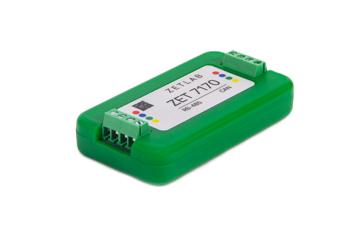
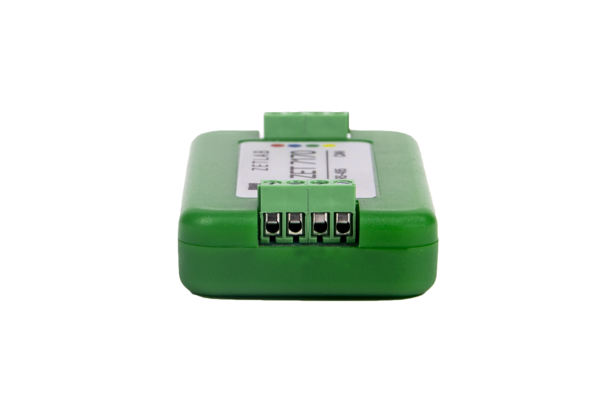
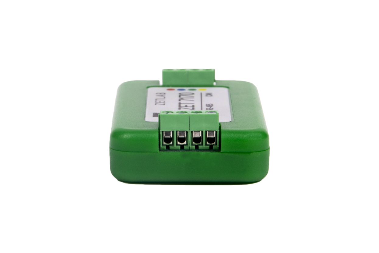
Interface converter ZET 7170

  • Interface converter RS-485 → CAN;
  • Connection of transducers with Modbus RTU protocol;
  • Integration of third-party transducers into CAN measurement line;
  • Simplicity of use and software support of various devices.

POR

(price on request)

Specifications

of Interface converters ZET 7170

Interface of connection to digital transducers
Intelligent sensors connection interface RS-485
supported protocols Modbus RTU
Data rate 4800, 9600, 14400, 19200, 38400, 57600, 115200 бит/с
Data transfer interface
Measurement line connection interface CAN 2.0
Data rate 100, 300, 1000 kbps
Operational parameters
Dimensions 71×39×17 mm
Power supply 9 -24 V
Maximal consumed power 1 W
Maximal consumed power of the connected transducer 5 W
Reverse polarity protection available
Weight 30 g
Operating temperature range  -40 … +60 °С
Electromagnetic compatibility (EMC)
IEC 61000-4-2, ESD contact 4 kV, air 8 kV
IEC 61000-4-4, EFT power 0,5 kV, signal 0,25 kV
IEC 61000-4-5, Surge 500 V

AVAILABLE PRODUCT VERSIONS

Standard: laboratory product version, plastic casing (green color).

ОЕМ: circuit without package.

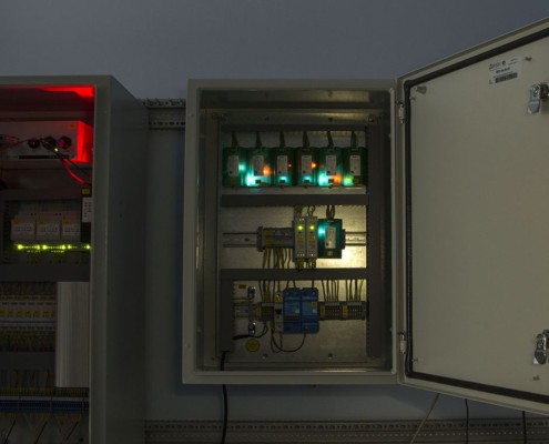
Industrial*: standard module is placed inside of a leak-proof casing (transparent cover).

*The price is calculated on individual basis

Operating principles

of Interface converters ZET 7170

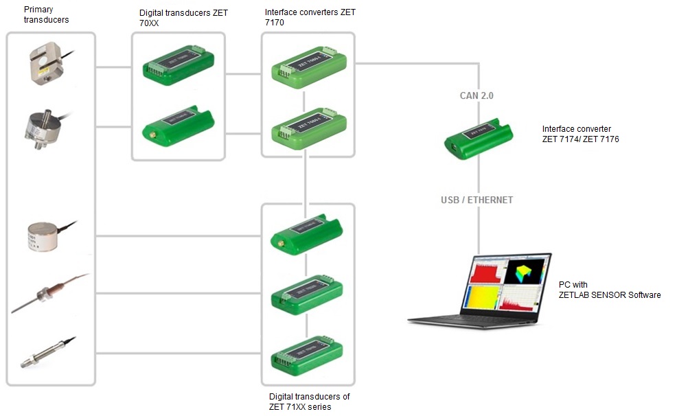
In order to connect digital transducer with RS-485 interface to measurement line with CAN 2.0 interface, it is necessary to install ZET 7170 Interface converter between them. One interface converter ZET 7170 supports connection of a single digital transducer with RS-485 data interface. If you need to connect several digital transducers to the measurement line, it is necessary to connect ZET 7170 interface onverter to each digital transducer.

Interface converter ZET 7170 is connected to the measurement line as a usual digital transducer with CAN 2.0 interface and takes two addresses in the measurement line.

Scheme of connection to the measurement network

for Interface converters ZET 7170

Scheme of connection to the digital transducers

ZET-7170-connection to digital transducers

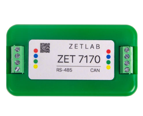
Contacts for connection
to digital transducers

Designation of output connections to be used for connection with digital transducers 

Contact Designation Labelling
1 +(9…24) V Red
2 RS-485 line «DATA-» Blue
3 RS-485 line «DATA+» Green
4 GND Yellow

Scheme of connection to the measurement network

ZET-7170-connection to digital measurement network

Contacts for connection
to the measurement network

Designation of output contacts used for connection to CAN 2.0 line

Contact Designation Labelling
1 +(9…24) V Red
2 CAN 2.0 line «H» Blue
3 CAN 2.0 line «L» Green
4 GND Yellow

Structural scheme of measurement network

Structural-scheme-of-establishing-measurement-circuits-based-on-ZET-7170-interface-converters-1

Control

of Interface converters ZET 7170

The required settings are saved in the memory of Interface converter ZET  7170 upon completion of the manufacturing process. In the case if you need to configure the settings of the converter (for instance, if the type of the transducer used is changed), you can do it by connecting the device to the PC via interface converter and activate the program “Device manager”.

Configuring the Interface converter

Configuring of the interface part is implemented in compliance with the instructions specified in the document “Interface part configuration of the digital transducers of ZET7xxx series”.

Please, note, that in in the field “Address (node) 2-63” of ZET 7170 “Information” tab it is necessary to set the unique address of the device in the measurement line. Unique addresses of all the devices in the measurement line are required for proper operation of the measurement line. The addresses of the devices should be set in the range from 3 to 63.

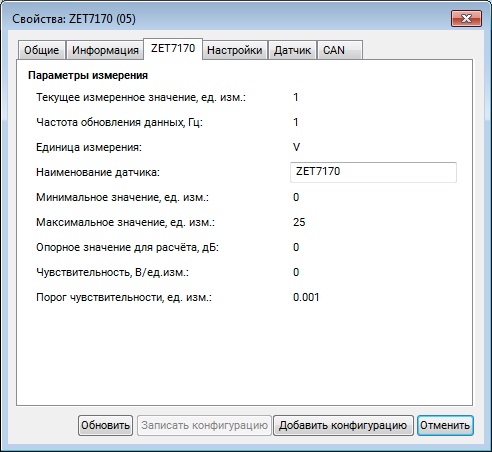
Tab «ZET 7170»

Tab «ZET 7170» contains information concerning parameters of the device:

Вкладка «ZET 7170»

Parameter Possibility of configuration Admissible values Description
Current measured value
(in measurement units)
Within the measurement range The parameter displays the number of new values received from the interface converter and the digital transducer connected to it.
Data rate, Hz The value corresponds to the sampling frequency of the interface converter.
Measurement unit The measurement unit of the parameter “Current measured value”.
Name of the transducer Yes Any sequence of the symbols
(max. 32)
The name of the interface converter. The name of the interface converter. The parameter is arbitrary assigned.
Minimal value,
in measurement units
The section contains the minimal possible value that can be measured by the interface converter in the particular channel.
Maximal value,
in measurement units
The section contains the maximal possible value that can be measured by the interface converter in the particular channel.
Reference value, dB The section displays the reference value required for representation of the measured value in dB.
Sensitivity, in measurement units The parameter displays sensitivity value.
Sensitivity threshold, in measurement units The parameter specifies accuracy of measurement performance.

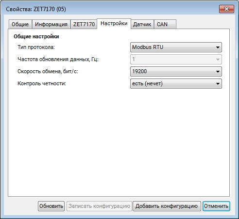
Tab «Configuration»

The tab “Configuration” contains the information concerning interface parameters of the connected transducer.

Вкладка «Настройка»

Parameter Possibility of configuration Admissible values Description
Protocol type Yes Modbus RTU
Dimetrix DLS-FLS
Protocol type of the digital transducer connected to interface converter ZET 7170
Data rate, Hz No 1 Sampling frequency of the interface converter
Baud rate, bps Yes 4800
9600
14400
19200
38400
57600
115200
Data exchange rate between interface converter ZET 7170 and the digital transducer connected to the interface converter
Baud rate of the digital transducer is set in compliance with the data rate value set for the interface converter
Parity check Yes no
yes (odd)
The values of this parameter should be the same for the interface converter and the digital transducer connected to it

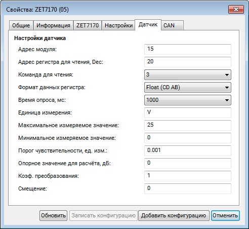
Tab «Transducer»

The “Transducer” tab contains the information related to the measurement channel parameters

Вкладка «Датчик»

Parameter Possibility of configuration Admissible values Description
Module address Yes 1-246 Address of the digital transducer connected to interface converter ZET 7170
Register address, Dec Yes Register address of the digital transducer to be acquired.
The parameter is specified in the digital transducer certificate.
Command to read Yes 3
4
Modbus commands for reading the register
Register data format Yes Float (AB CD)
Float (CD AB)
Float (DC BA)
Int32 (AB CD)
Int32 (CD AB)
Int32 (DC BA)
Int16 (AB)
Int16 (BA)
Byte sequence of the register
The parameter is specified in the digital transducer certitificate
Polling rate, ms Yes 1000
100
10
Register polling rate
Measurement unit Yes The parameter corresponds to the the measurement unit of the digital transducer connected to the interface converter.
Maximal measured value Yes The section depicts the maximal possible value, that can be measured by the digital transducer in the particular channel.
Minimal measured value Yes The section depicts the minimal possible value, that can be measured by the digital transducer in the particular channel.
Sensitivity threshold, in measurement units Yes The parameter specifies accuracy of measurement performance.
Reference value for calculations, dB Yes The parameter specifies the reference value required for representation of the measured value in dB.
Conversion ratio Yes Multiplying ratio
Offset Yes Additive ratio

Basic configuration

of ZET 7170 Interface converter

Вариант базовой комплектации

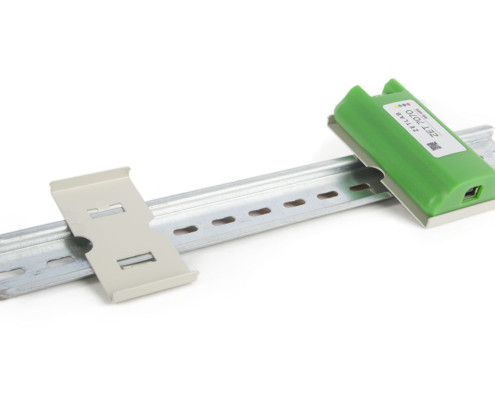
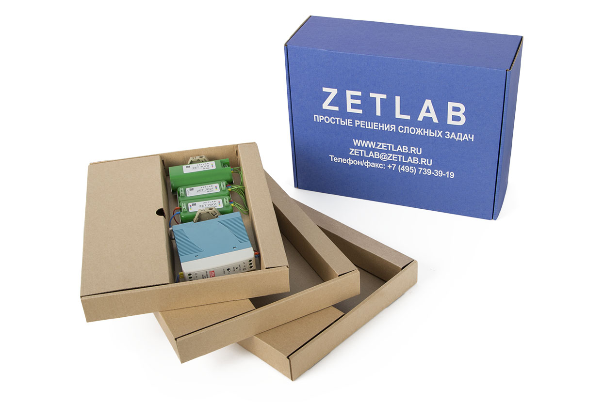
The delivery scope of ZET 7170 Interface converters includes:

  • Interface converter ZET 7170;
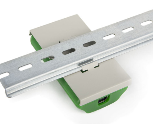
  • DIN-rail mounting panel for plastic modules 71×39 mm;
  • Set of operational documentation.

Order form - If you want to place an order or to make a request regarding technical specifications of particular product, fill out the form below: