Rules for SHM system development
with the use of cloud technologies
Basic principles of SHM system development with the use of cloud technologies:
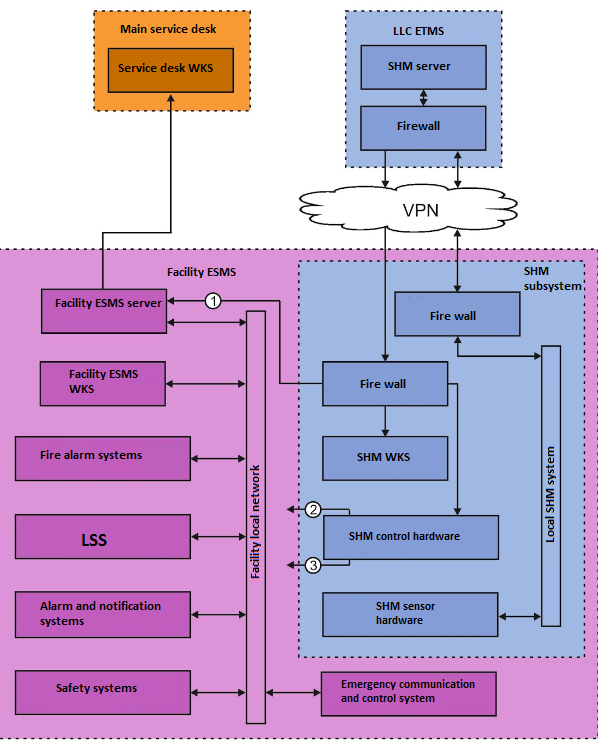
- The transducers are distributed along the controlled object, thus forming the measuring lines. The measuring lines are further connected to interface converters inside of the data acquisition nodes electrical cabinets.
- In the case, if the SHM system has several measuring lines, they are interconnected into a single local SHM network with Ethernet protocol.
- Local SHM network is connected to the Internet via a firewall forming a VPN connection with ZETLAB server.
- The information from the transducers is sent to the server for recording and further processing.
- Current operational state of the SHM system components and the registered signals processing results are sent via VPN connection to the SHM WKS for visual representation and analysis.
- The alarm notification signals from SHM server can be sent to ESMS server via MODBUS TCP, OPC UA, OPS DA protocols as well as to additional SHM system equipment via dry contacts or via MODBUS RTU protocol.
Structural scheme

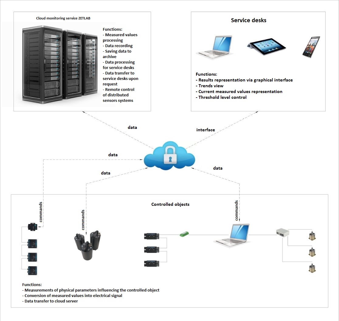
Based on the requirements of the design documentation, there is established a measuring system based on the transducers manufactured by ZETLAB Company (e.g., deformation sensors ZET 7010-DS, tilt meters ZET 7054, three-axial seismic recorders BC 1313 and other transducers depending on a particular task). The measured physical values are further converted into a digital signal (the conversion can take place inside of the transducer or in the data acquisition node).
The digitized data of the transducers is sent to ZETLAB server as a constant data flow via Internet. Depending on the particular features of the measuring system, the data can be sent to the server directly or via a PC used as a local data acquisition device.
In order to provide uninterrupted data transfer to the cloud server, it is necessary to provide an Internet data communication channel. Data transfer speed of the channel is calculated individually for each particular case and depends on the number of the transducers used. Data transfer speed of the channel (kbps) can be calculated by the formula:
V=0,32*F*N, where
F – stands for the sampling frequency of the transducer;
N – is the number of measuring channels.
Data communication channels requirements
| № | Sensor type | Recommended data communication channel, kbps |
| 1 | BC 1313 | 128 |
| 2 | ZET 7152-N / ZET 7156 | 96 |
| 3 | ZET 7150 | 32 |
| 4 | ZET 7052-N | 9,6 |
| 5 | ZET 7054 / ZET 7154 | 0,64 |
| 6 | ZET 7010 DS / ZET 7110 DS | 0,32 |
| 7 | ZET 7080-I / ZET 7180-I | 0,32 |
| 8 | ZET 7080-V / ZET 7180-V | 0,32 |
| 9 | ZET 7012-V / ZET 7112-V | 0,32 |
| 10 | ZET 7020 / ZET 7120 | 0,32 |
| 11 | ZET 7012-I / ZET 7112-I | 0,32 |
Note: the total width of the data communication channel is calculated from the sum of the data communication speed for each of the sensors of the measuring system.
The transducers data is sent to ZETLAB server for further recording, processing, and storage. The server can also be used for remote control of the transducers. In the case, if it is necessary to change the configuration of the transducers, e.g., in the course of a remote metrological self-check, then the corresponding signals can be sent from the server to the transducers.
Upon request of the user, the server sends the processed data to the WKS. Thus, the user does not have to process the data: the cloud server provides processed data via the graphical interface, WKS, trends, current measurement value, alarm signal, etc.
Internet is used for data transfer from the server to WKS. As a WKS it is possible to use any device with Internet access, e.g., PC., smartphone, tablet PC. It is recommended that the data communication channel between ZETLAB cloud server and WKS should have data communication speed over 10 Mbps.
All the data is transferred via a closed communication channel and a firewall created by the VPN-tunnel. It allows to guarantee safe data storage and transfer.

