
Motion control and positioning of stepper motor using ZETVIEW software
Nowadays automated control systems are widely spread and it is hardly possible to find a sphere, where there would be no need to implement automation of some process.
When considering motion, displacement and positioning control, it is possible to outline several subjects of research, while each of them requires a scientific approach, for instance: electrical shafts rotation speed control, precise positioning of stepper motor control for the purpose of their further implementation in various automated systems, etc. It is noteworthy that as a research subject we may also consider the whole system in general.
Since there is a high demand for stepper motor control and positioning system, let us consider creation of a universal system,which would allow to set various operation modes of the motor and to control it by means of ZETLAB and ZETVIEW software.
General scheme of universal measurement and control system is shown in Figure 1.
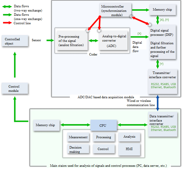
Figure 1 – Overview of universal measurement and control system
System structure depends on a particular controlled object. For the purpose of data acquisition various sensors are used (primary transducers, producing output value as a change of electrical potential (or a current), degree of which is proportional to the impact on the sensor). Electrical potential is transferred from the sensor to data acquisition mode, based on ADC conversion. This part of the system is intermediate between the sensor and controller, performing mathematical processing of the signal and producing controlling action. In its turn, data acquisition module is a complex device consisting of several parts: preliminary processing module and ADC converter. The data in digital format is transfered to the digital signal processor and communication line for further mathematical processing. Integrated microcontroller controls signal transmission and operation of data acquisition module. Sensor signals in digital format are transferred to the communication line. Communication lines can be both wired and wireless. As a basic element of communication line one can use the following options:
- RS-232;
- RS-485;
- USB;
- Ethernet;
- Bluetooth;
- Wi-Fi
- and other.
All the subsequent mathematical processing of the signals is performed by the microcontroller or a PC. It is at this stage that the control algorithm software realization and control signal forming take place. The signal is then sent to the control module, which, in its turn, controls the stepper motor.
In order to analyze system structure and composition of the stepper motor control system based on universal measurement and control system, let us consider it in more details.
Stepper motor is an electromechanical device converting electrical signals into discrete mechanical motion. There are three types of such electrical motors: with alternating magnetic resistance, with constant magnets and hybrid systems.
For the purposes of this research we will consider stepper motor with constant magnets and two independent windings. It consists of a stator, windings and a rotor with constant magnets. Alternating winding poles have rectangular shape and are placed in parallel to motor axis. Magnetization of the rotor in such engines provides powerful magnetic flow and higher output if compared to stepper motor with alternating magnetic resistance. An example of stepper motor with constant magnets is shown in Figure 2.
Depending on motor windings configuration, the motors are classified into bipolar and unipolar. Bipolar motor has one winding per phase. In order to change the magnetic flow direction, the controller should change the polarity of the winding. For this type of the engine it is necessary to use bridge- or half-bridge circuit with bipolar power supply. Bipolar motor has two windings and four outputs respectively. Unipolar motor also has a winding for each phase, but there is also a winding tap. It allows to change magnetic field direction formed by the winding by simple switching between winding sections. This feature considerably simplifies the control process. The circuit should have 4 simple keys. Thus,unipolar motor implements a different approach to changing the direction of the magnetic field. It is possible to connect the winding taps, thus, the motor may have 5 or 6 winding taps. The circuit diagram of the stepper motor is shown in figure 3.
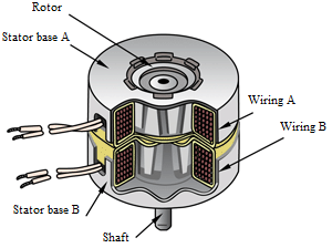 Figure 2. Stepper motor with constant magnets |
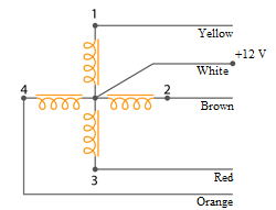 Figure 3. Principal scheme of unipolar stepper motor with 5 taps |
In order to develop the control system, we are going to use Sankyo MSJE200A53 stepper motor (unipolar stepper motor with constant magnets, two independent windings and 5 winding taps).
One of the key points for the system development is the choice of the hardware to be used in the control system. Since the circuit should have 4 simple keys to supply voltage to stepper motor windings, one can use IC chip ULN2003, consisting of a set of powerful keys with protective diodes at the output. Protective diodes of IC chip ULN2003 allow to connect high inductive loads without protection from inductive kick.
In order to supply control signals to inputs 1… 4 of the IC chip, one can use ADC-DAC module ZET 210, equipped with a digital port, which seems to be the most appropriate for the system in question. Outputs of ZET 210 meet the requirements of TTL 3.3 В, thus, they can be used for control keys switching of stepper motor and ULN2003 (12V).
Thus, the general overview of the stepper motor control system is shown in figure 4.
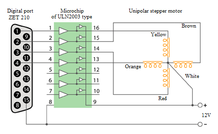
Figure 4. Stepper motor control system
In the case if module ZET 210 is used, it is possible to increase the amount of system functions, since ADC DAC module is intended for measuring primary transducers signals parameters in wide frequency range (with sampling frequency up to 400 kHz – the value to be set by the user depends on a particular task). In the stepper motor control system the following sensors can be used:
- potentiometer— as a position sensor for stepper motor magnetic poles (it is possible to enhance control precision by means of analyzing potentiometer values);
- RPM sensor — to control stepper motor rotation in constant operation mode.
Wide dynamic range of ZET 210 input channels allows the user not to adjust amplification ratios, which can be useful for connection of various sensor types. The module operates in the mode of constant input/output signals transfer to PC memory with the possibility of further digital processing of the signals. Digital processing of the selected signals is performed by means of sequential connection of the keys and one ADC converter. The module has successive approximations ADC unit. ADC module is used for digital processing of constant level and alternating voltage signals. It is possible to connect several ADC DAC modules to a single PC, thus establishing portable measuring systems.
After having selected the hardware components of the system it is necessary to choose appropriate software. SCADA-system ZETVIEW is optimal variant for the software component of the system. SCADA-system ZETVIEW is highly effective graphical programming environment allowing to create flexible and scalable applications for measurements, control and testing purposes with minimal time and monetary expenses. As a rule, SCADA-system ZETVIEW is used as a system for acquisition and processing of the data obtained from the devices connected to the PC. Flexible and scalable features of SCADA-system ZETVIEW allow to implement it at all stages of the technological processes – from modeling and development of prototypes up to large-scale operational tests. Implementation of SCADA-system ZETVIEW integrated environment for signals measurements and results processing increases overall efficiency of the industrial process.
Along with this, SCADA-system ZETVIEW is a simple and user-friendly system. Ordinary user without any skills in programming can quickly (from several minutes up to several hours) create a complex program for data acquisition and objects control with user-friendly interface. The resulting applications can be used offline (without ZETVIEW programming environment), which considerably simplifies use of the application and corresponding training.
For the purpose of stepper motor control algorithm implementation using ZETVIEW program modules, there should be created a project for motor control with the possibility of setting shaft rotation modes, change rotation speed and put the shaft into reverse. Implementation of SCADA-system allows the user to change the automation logics of measurement and control process, program interface as well as to customize the system if the need be.
Logical scheme of the control system operation within the framework of SCADA-project “Stepper motor control” consists of several modules interconnected with communication lines. The key element of the scheme is the “Control module”, which establishes the link between the user setting the control impact and the controlled object. Diagram of system implementation is shown in figure 5.
Figure 5. Stepper motor control system logics within the framework of SCADA-project ZETView.
From the diagram shown in figure 5 one can see that the stepper motor control system is rather simple, has linear and sequential structure. The project contains several module types:
- control modules — elements allowing the operator to set control impacts (start, selection of rotation direction, speed and mode, etc.);
- indication modules — elements used for displaying various process states (indicators of control lines state);
- mathematical and logical processing modules— intermediate auxiliary elements allowing to implement control algorithms (mathematical and logical multiplication, addition, keys, etc.);
- instrument communication modules — elements enabling communication with hardware components of the system (digital ports, measuring channels, ADC channels, etc.).
By means of connecting these modules sequentially there is established an integral system – a program having a mnemonic scheme as a program code and ZETVIEW as implementation environment.
Before putting the system into operation it is necessary to set the user interface. The user interface is shown in figure 6. The operator can start stepper motor control algorithm by means of corresponding key, select direction of shaft rotation, rotation mode (using combobox), as well as to view controlled device lines state (control module – digital port ZET 210) in corresponding indicators.
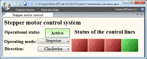
Figure 6. User interface of stepper motor control system in SCADA-system ZETView.
SCADA-system ZETVIEW has several instruments for enhancement of stepper motor control system features. Depending on particular task, the end user can increase system operation logics and customize program interface. Taking into consideration modular and universal features of the system, it is possible to establish automated system for technological processes control. Wide application range of the system encompasses machinery operating in constant mode, technological processes automation, including microelectronics industry. Feedback communication also allows to implement various control algorithms, for instance, PID-control.
Authors: A. Antonov, A. Krasovskiy