
CONNECTING ZETSENSOR TO TRACE MODE
via Modbus
This document describes connecting the ZETSENSOR digital sensor via the Modbus protocol using ZET 7070 (USB-RS485) interface converter in the TRACE MODE integrated development environment. The following combination will be used as an example: ZET 7070 (USB-RS485 interface converter) +ZET 7052 (digital triaxial linear acceleration sensor), as shown in Figure 1 below.
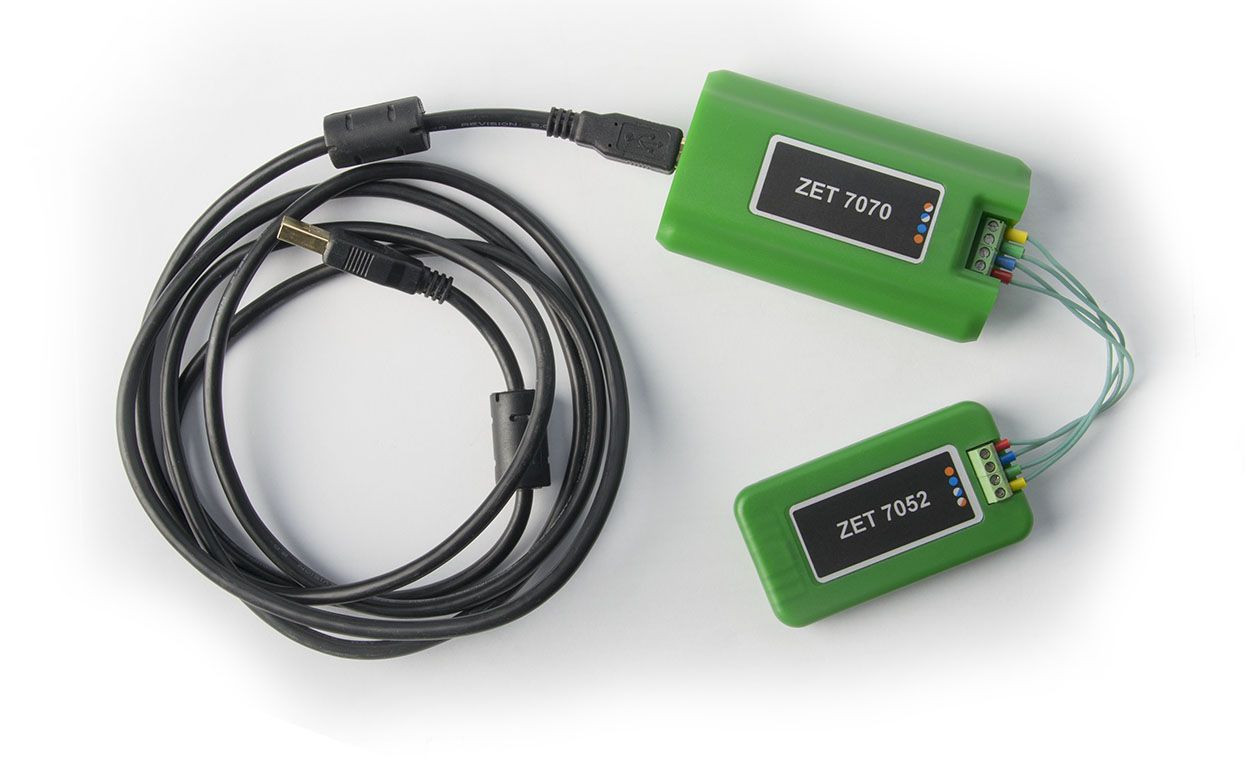
Figure 1
To activate ZET 7070 in the TRACE MODE environment, load VCP driver for this unit: this will make it possible to work with the converter like with a COM port. For this, select ZET 7070 (ZET Sensor USB) in the Device Manager, right-click and select “Properties” (Figure 2).
Check the “Load VCP” on the “Advanced” tab of the “Properties: ZET Sensor USB” window, and press “OK” (Figure 3).
After the device has been re-connected, the relevant COM port will appear in the Device Manager (Figure 4).

Figure 2

Figure 3

Figure 4
Note: any third-party device with RS-485 interface can be used as a converter for connecting the ZET 70xx sensors.
Then proceed as instructed by the training film demonstrating equipment connection via RS-232/485 serial port using MODBUS RTU protocol (//www.adastra.ru/products/drivers/modbus/).
1) Add Modbus group to “Sources/Receivers” and create three components (for X, Y, and Z axes of the linear acceleration sensor) Rout_Float(3) for reading 4 bytes with conversion to the float using the ReadHoldingRegisters command. Configure each component (Figures No 5, 6, 7). Take the sensor axis name as the name. Port number for each component shall be 0x8 (COM9). Device address in the MODBUS network: 0x2. Configure the data reading register address (channel) according to the register table for the SET 7052 sensor.
Note: register address tables for ZET 70xx sensors are provided in the Modbus address tables for ZETSENSOR units section, or generated using the SensorWork after connection to a PC. A part of a generated table is shown in Figure 8.
For X axis the address will be 0x14, for Y, 0x3a, and for Z, 0x60. All other settings should remain unchanged.

Figure 5

Figure 6

Figure 7

Figure 8
2) Move the three created components to the “Channels” group of the “RTM_1” node (Figure 9). The settings of each of the three TRACE MODE channels should remain by default.
3) Create a COM ports group in the “RTM_1” node. Open the created COM port for editing and configure it (Figure 10). The port number shall be COM9, rate, 19,200 bps, parity check, 8-1-o. Check the CRC. All other settings should remain unchanged.
Note: some sensor settings such as rate and parity check can be read from the sensor using the SensorWork tool. Parameters are configured in the sensor using the standard software ZETLAB SENSOR included in the delivery package.

Figure 9

Figure 10
4) Configure the work display to show three text fields where the current sensor reading will be displayed, as well as the trend for tracking the acceleration values dynamics over time (Figure 11).
5) Save the project to the hard drive and for the real-time monitor. Start the profiler. The result of operation is shown in Figure 12 (sensor position in space was changed during the recording).

Figure 11

Figure 12