
Connecting ZETSENSOR in MasterSCADA
through OPC server
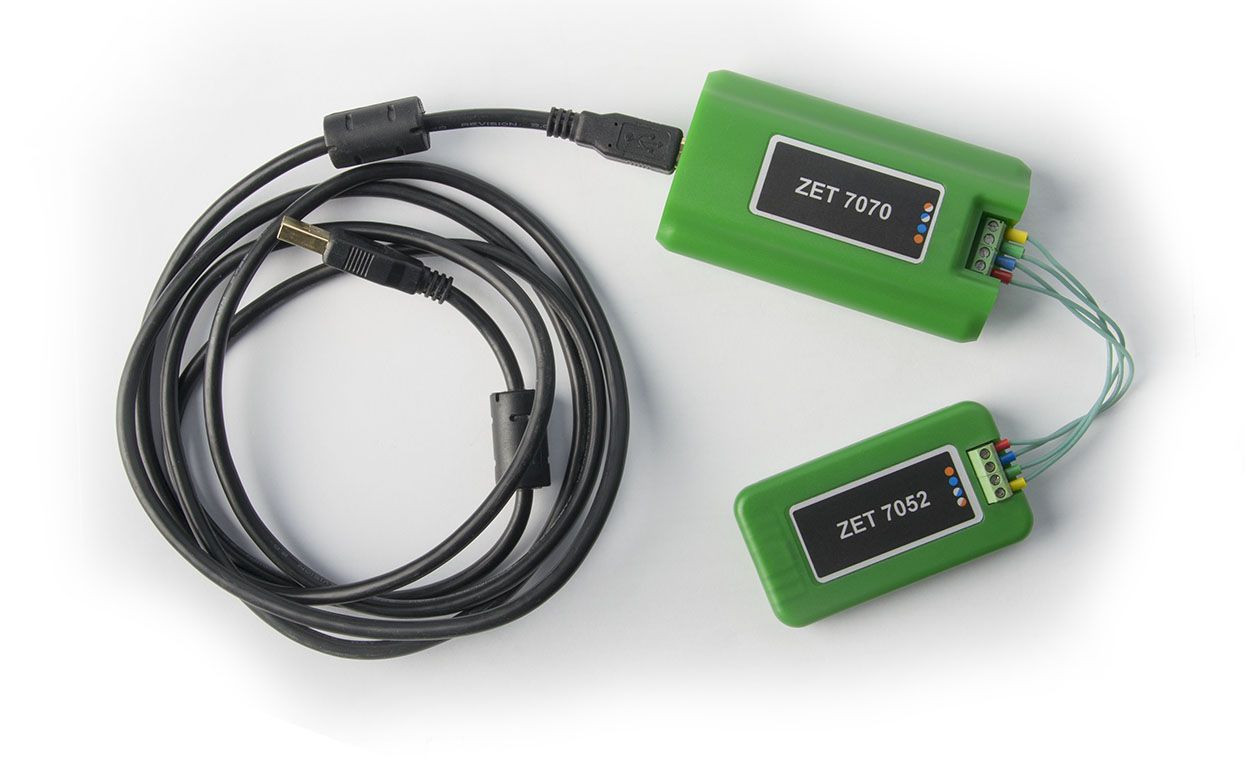
Figure 1
First, configure the ZET.7xxxOPC OPC server to work with the selected devices. For this, launch the SensorWork program included in the sensor package, search for the devices (Figure 2), activate OPC server mode (Figure 3), check the data in the OPC tags (Figure 4), close the “Work with OPC server” window, configure the program for launch in OPC server mode for the next time (Figure 5).

Figure 2
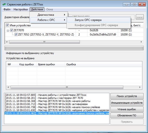
Figure 3

Figure 4

Figure 5
Then, proceed as instructed in the training video demonstrating equipment connection via the integrated OPC client of MasterSCADA ((//www.youtube.com/watch?v=a4Hk_a_BbGQ):
1) Add a “Computer” node to the “System” tree with the name of “Computer 1”. Add the ZET.7xxxOPC OPC server to the “Computer 1” node and add all variables and groups to it (Figure 6).
2) To generate an objects tree, create an “Acceleration” node in the “Object” tree and set its running on all computers (Figure 7). Add a “Value” in the “Acceleration” node for each of the three OPC tags and name them “X”, “Y”, and “Z”, respectively (Figure 8). Add relation between the object node “X”, “Y”, and “Z” values with the relevant OPC tags of the system node (Figure 9).

Figure 6

Figure 7

Figure 8

Figure 9
3) Generate the node mnemonic to display the trends for each acceleration value along X, Y, and Z axes (Figure 10).
4) Save the project to the hard drive. Launch the project. The result of operation is shown in Figure 11 (sensor position in space was changed during the recording).

Figure 10

Figure 11