ZETLAB object state monitoring system
Process facilities state monitoring is one of the key aspects of industrial and ecological safety. One of the major applications of this technology is the petroleum industry pipeline systems monitoring. There are several factors influencing the pipelines technical state. One of them is the seismic impact resulting in stress and strain state of the pipelines. ZETLAB process facility state monitoring system is used for measurements of stress and strain state caused by seismic impact.
Seismic stations with sets of triaxial seismic sensors are used as a source of data for calculations performance. The Software “Seismic impact control system” (hereinafter referred to as SCS Software (seismic control system) uses the seismic stations’ data for the purpose of earthquake focus detection. Dedicated software “Pipe sections control”uses the seismic station’s data and Shaker Controller Software information to calculate the stress-strain state of the pipelines and to produce a test protocol.
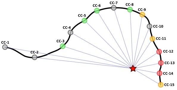
Seismic stations located along the pipeline or close to it are connected to the pipeline at certain intervals. Thus, the pipeline represents a coordinate axis with seismic stations, while the coordinates values correspond to those of distance.
The seismic stations are used to detect (record) and to fix any seismic events within the specified area (as well as to distinguish between false and real events, earthquakes and local vibrations). In the case, if the seismic event has not been registered by a seismic station due to technical issues or seismic event weakness, then the seismic event values can be calculated based on data received from adjacent seismic stations. In the case, if a seismic event has been registered by three or more seismic stations, then the SCS software is able to detect the earthquake focus. In this case, the pipe section control software performs the following scenario:
In the case, if the earthquake focus has been detected, then the pipe section control software is able to evaluate impact level to the pipeline at each point. To do that, the pipeline section control software analyzes vibrational level of the seismic stations which failed to detect this seismic event.
All the seismic stations are arranged in accordance with their remoteness from the earthquake focus location. Based on the obtained magnitude level at the earthquake focus area and acceleration values at the seismic stations which detected this seismic event, it is possible to calculate the acceleration level at the remaining seismic stations.
In order to estimate the seismic intensity value, one can use Shebalin formula in its general variant [1, 2]:
In = 1.5M – 3.5lg(Dn) + 3
An = 0.0078eInln2
where:
In – intensity level by MSK-64 scale;
M – earthquake level on the Richter scale;
Dn – distance from seismic station to earthquake hypocentre;
An – seismic station peak acceleration value.
If the intensity value is known, it is possible to estimate the acceleration value registered at the seismic station location. For this purpose, a converse formula is used [3].
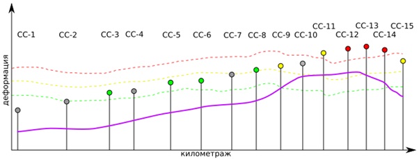
Then we have to calculate deformation ratio for each of the pipelines sections. To do that we have to perform linear interpolation of acceleration values in accordance with the readings of two adjacent seismic stations. Deformation ratio can be obtained using a simplified formula:
χ = acT/Cp
where:
ac – acceleration vector (from the previous formula) projection at pipeline section single vector;
T – basic periods maximum value for axes;
Cp – extension wave speed (corresponding value can be found in the table below)
| Ground type | Extensional wave speed – km/sec |
|---|---|
| sandy, water – saturated | 0,35 |
| loose damp sand | 0,12 |
| sand clay | 0,3 |
| moist clay, laminated | 0,5 |
| clay, hard & semi-hard | 2,0 |
| frozen soil | 2,2 |
| pebble gravel | 1,1 |
| limestone, shale, sandstone | 1,5 |
| monolithic rock base | 2,2 |
The seismic stations can be in on- and off-mode. If a seismic station transmits data to SCS software, it is considered to be in on-mode, otherwise, the seismic station is considered to be in off-mode. If the seismic station data transfer failure is due to communication line defect, then in the current pipe section control calculations this station is considered to be in non-operational condition. Upon communication line recovery and data transfer renewal, the calculations have to be performed with regard to recently received data.
Active seismic stations may detect seismic events (i.e. to determine phase time, peak acceleration and basic oscillations period) as well as to omit them due to a number of reasons. Pipe section control software should have certain time interval within which data receipt from seismic stations is expected. As SCS Software detects a seismic event, pipe section control software should start receiving data from active seismic stations during a certain time interval. Active seismic stations that failed to obtain seismic event parameters should not transmit any data while pipe section control software should assign zero values for the corresponding parameters. Inactive seismic stations have to be excluded from the calculation process.
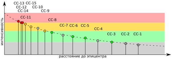
In Figures 1-3 seismic stations that failed to receive seismic event parameters are marked with grey color. However, pipe section control software still has to perform parameters interpolation for the seismic stations that have not determined any earthquake parameters. Thus, Figure 2 shows a dependence of oscillations intensity on the distance to earthquake focus. The curve is based on oscillations intensity data received from active seismic stations while the unknown parameters have been calculated in accordance with the formulas listed below.
Software performance
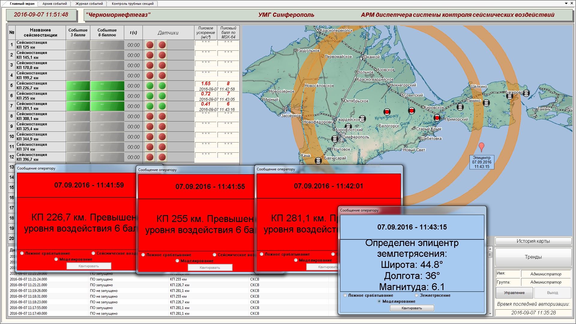
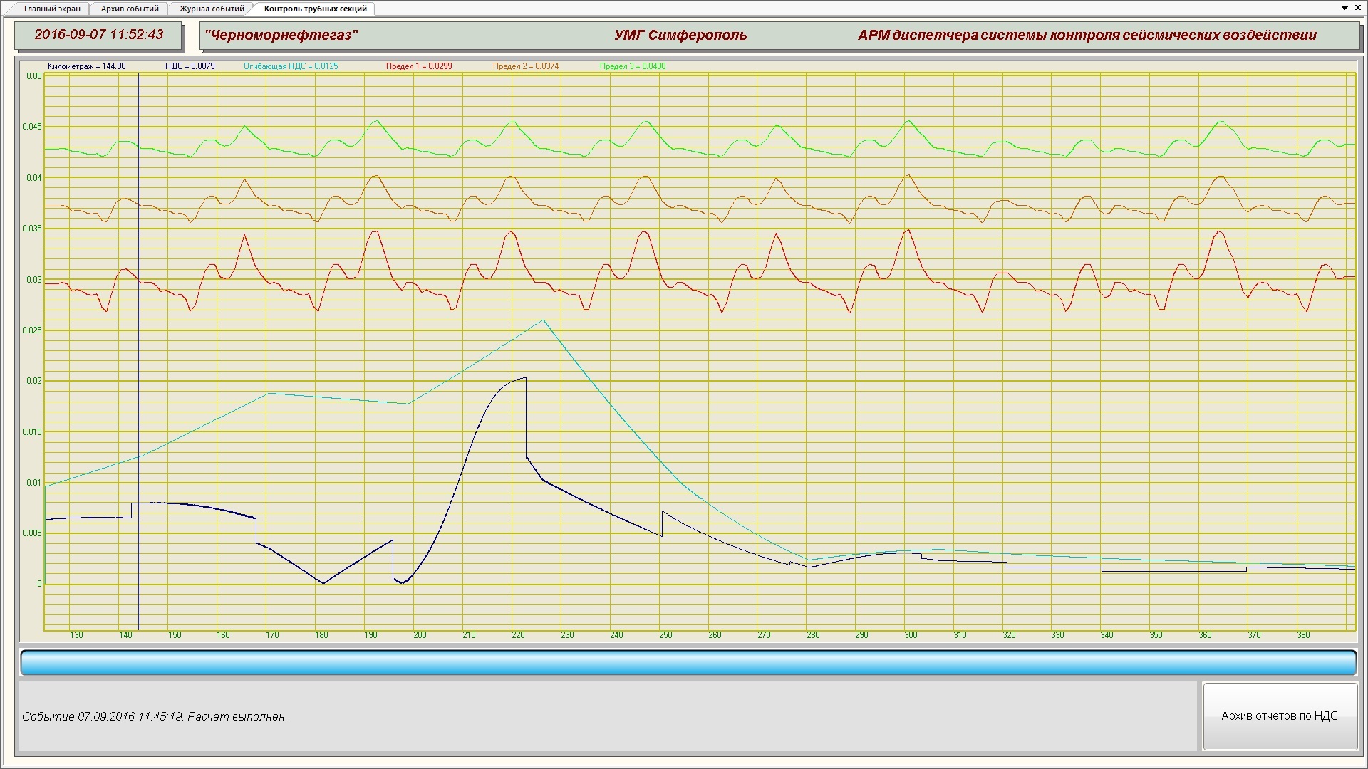
As an example we shall consider a monitoring system for the pipeline “Krasnodar territory – Crimea”. The first model case is an earthquake with a focus at 44.8° north latitude, 35.8° east longtitude, depth – 15 km, magnitude – 6.
As we can see from the Figure 5, the model earthquake has not resulted in exceeding the stress-strain state allowable standards.
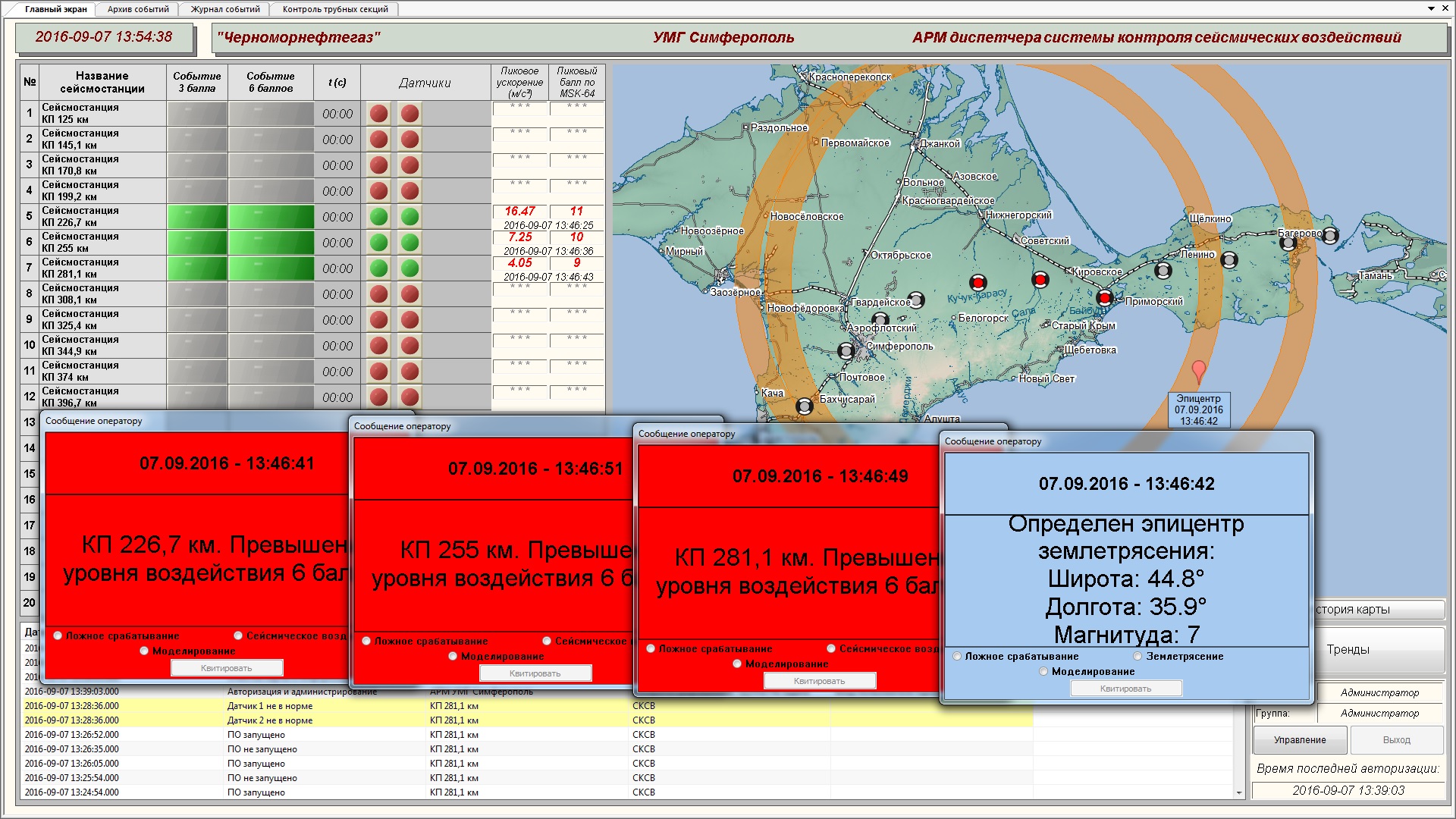
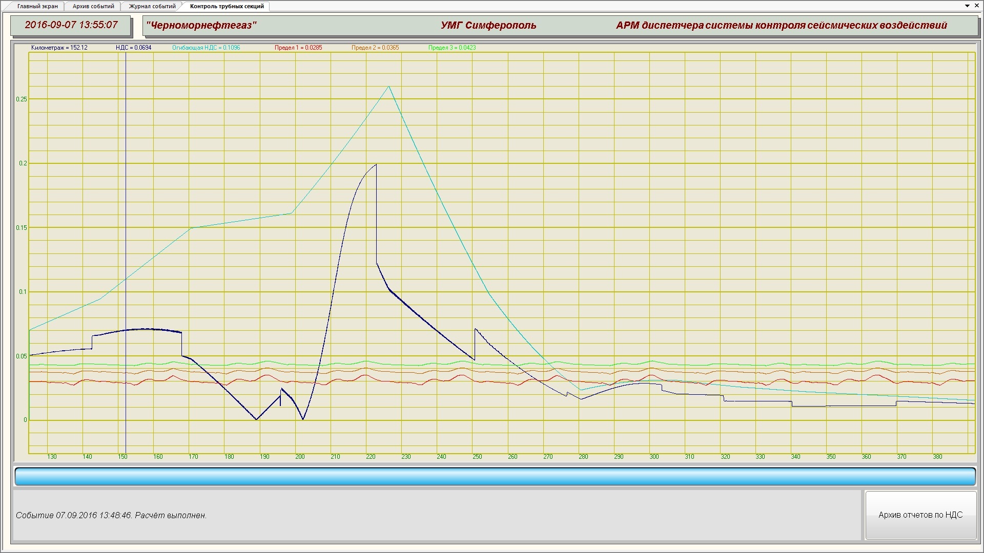
As a second model, we shall consider an earthquake with a focus at 44.8° north latitude 35.8° east longitude, depth – 15 km, magnitude – 7.
As we can see from Figure 7, the model earthquake has resulted in exceeding the stress-strain state allowable standards at certain sections, hence, it is necessary to check the pipeline sections which have critical stress-strain values.
References
1. Shebalin N.V. Methods of using engineering-seismological data in seismic zoning, Seysmicheskoye rayonirovaniye SSSR (Seismic zoning of the USSR), Moscow: Nauka, 1968, pp. 95–111.
2. Gorshkov, G. P., and Yakushova, A. F., General geology [3d ed.]. — M.: MGU, 1973. – 589 pp. 1973.
3. Seismic impact level evaluation methodics, ZETLAB Company, 2013, Attestation Certificate № 002-01,00260-2011-2013 от 20.12.2013.

