
Variety Of Strain Gauge Bridges
Why should one use a bridge instead of a divider?
It might seem that a voltage divider consisting of a resistive strain sensor and a fixed resistor (see Figure 1) would be sufficient for measuring the strain by means of resistive strain sensor.
R1 – fixed resistor, R2 – resistive strain sensor, R1=R2.
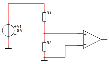
Figure 1. Divider with resistive strain sensor
Everything seems to be simple: strain causes the resistance, for example, to increase, and voltage at the midpoint also increases. However, if you actually assemble such circuit, you will face a few problems that will hinder the measurements or even lead to experiment failure.
The main disadvantage of this circuit is that the bias (rest) voltage considerably differs from voltage changes due to change in resistance of the resistive strain sensor. In other words, this circuit sets unreasonably strict requirements to the dynamic range of the measuring amplifier. For instance, when the divider is powered with 5.0 V DC voltage, it is necessary to measure at the 2.5 V level the voltages of mV units with precision of tens of µV, and this is at least 20 log2,5/10-6 ≈ 100 dB! It means that you need a fairly expensive amplifier with a wide input dynamic range.
However, there is a simple solution: adding one more divider to this circuit and measuring the signal between two midpoints which seems to be a quite elegant solution to the problem. Let us consider this circuit in Figure 2. R1 and R2 resistors have a purpose similar to the previously considered circuit. R3 and R4 resistors act as fixed resistors. R1=R2=R3=R4.
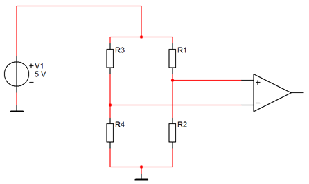
Figure 2. Strain gauge bridge
In an ideal scenario both inputs of differential amplifier with the unloaded resistive strain sensor should have the same voltage. In reality, there is a small voltage on the bridge, which is caused by resistances mismatching, also called the bridge unbalance. This voltage can be excluded by replacing one of the fixed resistors with a potentiometer or by deducting it from the result obtained.
Now we can perform measurements using the amplifier with a relatively narrow dynamic range, i.e. we can simplify the requirements for measuring amplifier.
If classifying this circuit according to the number of required connection wires, this circuit will be called a four-wired measuring circuit.
But this circuit is not perfect as well. The power supply voltage may change under the influence of different factors, which introduces errors to measurements. Besides, the wires from measuring bridge to the amplifier tend to be very long, and hence have some resistance that causes certain decline in power supply voltage. These factors must be taken into account in order to ensure more precise measurements. To compensate for these factors, it is sufficient to measure the actual voltage on the strain gauge bridge. To do this one has to add another differential amplifier to the circuit for measuring the bridge power voltage directly on the strain gauge bridge (see Figure 3). This amplifier has a wider absolute range of measurements than the measuring amplifier. If we calculate the number of wires coming from the measuring circuit to the strain gauge bridge, it will be clear why this circuit is called a six-wire measuring circuit.
However, that is still not as good as it gets. There is a following way to ensure even greater accuracy of measurements. All previous circuits utilized the strain gauge bridge power with DC voltage. But, as is well known, low-frequency part of spectrum contains considerable amount of thermal and other noise. By powering the strain gauge bridge with AC current, while shifting the operating frequency range to high frequencies, you can increase the signal-to-noise ratio, thus enhancing the measurements accuracy. To do this, select the spectrum window with low noise.
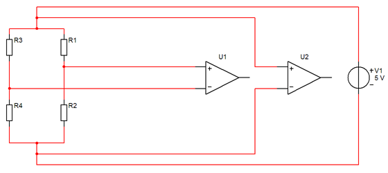
Figure 3
These circuits have both advantages and disadvantages. The table below demonstrates them. We excluded the voltage divider circuit due to its incapacity.
| Circuit Type | Power Type | Accuracy | Frequency Range | Cost |
| Four-wire | DC | — | + | ++ |
| AC | — | — | + | |
| Six-wire | DC | + | + | – |
| AC | ++ | — | — |
See also
- Strain Gauge Measurements
- Theory of Strain Gauge Measurements, Layouts of Resistive Strain Sensor Connection to ZETSENSOR
- Layouts of Resistive Strain Sensor Connection to ZET 017-T8 Strain Gauge Module
- DIY Strain Gauge Weigher
- Establishment of Strain Gauge Bridge Circuits for Measuring Various Parameters
- Application of Resistive Strain Sensors for Measurement of Physical Values
- ZET 7010 Tensometer-485, a smart strain gauge sensor with RS-485 interface (static measurements)
- ZET 7110 Tensometer-CAN, a smart strain gauge sensor with CAN interface (static measurements)
- ZET 7111 Tensometer-CAN, a smart strain gauge sensor with CAN interface for dynamic measurements