
Vibration testing system
basic notions
In order to secure correct selection of the vibraton system components, which will be perfectly suitable for addressing the relevant task, it is necessary to have a general notion of the vibration tests, limit operational parameters of the system, and the mutual relations existing between the main vibrational parameters.
So, what are the parameters to be used for selection of the required shaker system?
Interrelation of force and vibrational acceleration
First of all, let us consider the relation between the impelling force and the vibrational acceleration in sinusoidal or random vibration mode.
The maximal acceleration depends on the impelling force and the weight of the specimen. In this case, we are going to use Newton’s second law of motion.
F = m * a
The maximal acceleration value specified in the shaker data sheet, can be achieved only without load, i.e., when the shaker motion is applied only to the weight of the shaker table. In the case, if load is used, the maximal acceleration value is to be calculated by the following formula:
a = F / (m0 + M + m)
where m0 is the weight of the shaker moving part, m is the weight of the fixture, M is the weight of the tested specimen. The total weght of fixture and the specimen should not exceed the mass specified in the data sheet of the transducer, otherwise the suspension of the shaker system may be damaged, which will result in warranty issues.
In the case of horizontal load, the counter-force will be applied to the shaker. Thus, it is necessary to provide reliable fixation of the shaker, or to buy a horizontal slip table from the manufacturer (in the case, if it is available for the particular mode of the shaker).
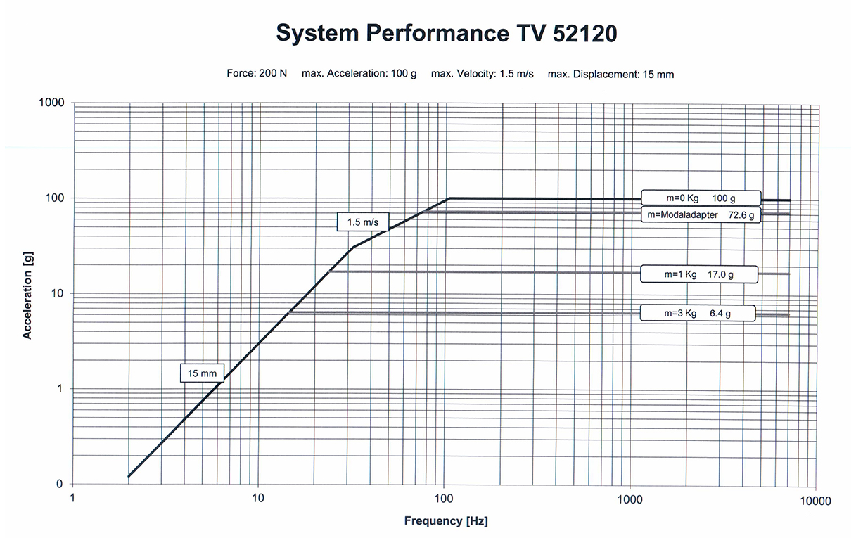
For the purpose of better understanding of the shaker limit characteristics, the operational documentation contains the chart of the shaker system performance. As an example, below you can see the system performance chart of system TV 52120:
Mutual relation of frequency, acceleration, and vibration displacement
Sometimes inexperienced users contact us with the following questons:
Specifications of the shaker for the sinusoidal vibration are as follows: frequency, amplitude, and acceleration, however, it is clear that the acceleration value depends on the two previous values… Could you please tell me what are the primary parameters of the shaker controller in the case of sinusoidal vibration? For instance, if we set acceleration and frequency, will the amplitude value be adjusted automatically? Am I right to think, that for TV 51120 with the load below 3 kg, the acceleration value up to 89g will be available throughout the specified frequency range (2… 7000 Hz)?
As we have already mentioned, the primary characteristic of the system is represented by the impelling force. This very value determines the maximal available acceleration of the shaker. In order to secure successful implementation of all the scheduled tests, it is necessary to evaluate the maximal profile acceleration and the maximal possible weight of the specimen to be tested. In the case if such shaker turns out to be unsuitable, then the impelling force has to be calculated individually for each particular test profile. The displacement amplitude depends on the configuration of the shaker (as an additional option, the manufacturer can increase the available displacement of the shaker). The frequency range is also determined by the design of the shaker, and the bigger is the shaker, the lower is its upper frequency limit. The bottom frequency limit depends on the amplifier.
You cannot achieve 89g at the frequency of 2Hz, since the displacement value in this case is going to be too big (more than 5 meters), however, at the frequency of 42Hz, the displacement will be only 12,5mm.
Also see the article “Sinusoidal vibration: mutual relation of acceleration, velocity and displacement“.
Ratio of shock and sine acceleration
What should we do in the case if we need to select a system for shock impact testing, and the data sheet of the shaker does not specify the maximal shock acceleration value?
What is the ratio of shock and sinusoidal acceleration, how to use the second law of motion in the case if there is no correlation between the specified impelling force of 200N and the maximal acceleration of 89 m/s2, for instance, for the shaker TV 51120? Or should we use the formula 200=89×[suspension mass]? But in this case, what is meant by the moving mass of 0,23 kg?
The ratio of maximal acceleration for sine signal and shock pulse is determined by the design of the shaker system and can vary from 20% up to 300%. In the case if manufacturer of the shaker does not specify acceleration or the impelling force for the shock impact, then you can use the relevant values specified for sine testing.
Effective moving mass is the weight of the shaker’s moving part to be considered when the test load is mounted on the shaker. Hence, Newton’s second law of motion is applicable in this case, however, it is necessary to calculate the moving mass value.
Spectral density as the vibration testing parameter
In addition to the sinusoidal vibration testing, the broadband random vibration testing is also a widely spread type of vibration testing. Now let us clarify what are the specific features of test profile calculation for this type of testing. To do that, we have to answer the following question:
How to select the shaker based on the required PSD for the broadband random vibration?
Based on the spectral density value, it is possible to determine the required acceleration and the frequency range. Normally, the frequency range is within the range of 10Hz – 2000Hz, which is admissible for any shaker. The total acceleration for the broadband random vibration testing is specified as RMS value. In the case if the manufacturer of the shaker does not specify the maximal acceleration for broadband random vibration testing, then it is necessary to use 50% of the specified maximal acceleration value.
In order to calculate the total acceleration based on the PSD chart, it is necessary to calculate the square of the figure below the graph and to invoke the square root from it.