
Unified test facility
of virtual measure gauges as part of hardware and software complex ZETLAB and ZETVIEW
It`s not a secret that the success of modern industrial enterprise depends on many factors: personnel qualification, factory load, market demand for output product, labor management etc. One of the key factors is the degree of industrial process automation at the enterprise that manufactures serial products.
Automatic management and monitoring systems are used almost everywhere in modern industry, and it is impossible to find production stage where there is no need for automation of one or another process. There are many objects of scientific research for people involved in developments in the field of automation at the enterprise, each of which requires peculiar approach, for instance:
- speed control of electric drives rotation;
- precise positioning of stepper motor armature to apply in the precise automation systems;
- temperature control of the working area to maintain a certain internal environment;
- control of electrical parameters of different automation devices and more.
Considering electronic industry as an example, we can distinguish one of the most popular areas in the field of automation of enterprises of this type. This area is creation and implementation of unified test facility of virtual measure gauges (UTF VMG). UTF VMG are implemented as a part of hardware and software of computer aids, the functions of currently applied monitoring and metering instrument to monitor radioelectronic components, building blocks and units and assembly units that are based on them. Test facilities provide complete automation of testing and measuring operations at principal stages of products manufacture, automated generation of test logs in specified formats and archiving of information in electronic format on technical information carriers.
Body
As a rule, basic universal test facilities of virtual measure gauges are created in two modifications: portable facility and stationary facility.
It is possible to distinguish two main components: hardware and software. The hardware part of unified test facility of virtual measure gauges consists of:
- industrial PC along with monitor and printer for test results registration;
- uninterruptible power supply;
- elements with A-to-D cards (ADC) realizing analog-to-digital conversion of signals;
- elements with cards of digital synthesis and signal generation and digital-to-analog conversion (DAC) of signals;
- transmatch.
Software part of the facility may vary greatly according to specific purposes, but in most cases it consists of:
- set of package drivers – operation programs of elements with cards of hardware part;
- applied software realizing virtual instrument with imaging tools of registered signals both in graphical and table form;
- custom-made software enabling to create automation-equipped working places of controller on technical process observation and operation thereof;
- databases of reference and registered signals;
- heavy-duty software enabling to perform arithmetic and logic operations and signal filtering from ADC units out of recorded files;
- self-testing program at starting of complex;
- program set in «Testing» mode;
- program set in «Debugging» mode;
- program set in «Repair» mode;
- reference signals editor;
- input signals editor;
- output signal editor.
Software part of the facility may vary greatly according to specific purposes, but in most cases it consists of:
The composition of hardware and software complex is determined by test object and is set by basic data of test object. Developed UTF VMG is a modified complex, its composition is determined by necessary for testing object set of modules with technical cards and relevant software.
Basic data for developing of unified test facility of virtual measure gauges is:
Products of unified test facility of virtual measure gauges provide performance of control and testing operations under conditions of factory run in the premises of workshops, laboratories etc., and also under the field (polygon) conditions.
Database of reference and registered signals provides recording and storage of signals is user-friendly. It includes search by date, signal identity and other attributes. The complex starts up when you turn on PC. Self-testing program starts automatically when the complex starts up and tests it for existence of necessary connections between units of the complex, power supply for all units and their functioning.
Program set in “Testing” mode provides full test of performance ability of the object under testing in automatic mode with display of notification on integrity and log delivery to the printer.
Program set in «Debugging» mode provides cascade analysis of object under testing with availability of displaying signals in graphic and table form. It also provides signal displaying in control points and comparison with its reference. As a rule, signal displaying is realized in real time with adaptation.
Program set in «Repair» mode provides search of defect part in «driven feeler» mode, in other words, it tells the operator at which control point the feeler should be set with printed-circuit pattern displaying and control point indication. The comparison between real signal and reference signal is provided by setting the feeler at reference control point.
Reference signals editor is able to correct reference signals using reference signal editor. The correction provides the ability to form new signals of any form.
Input signal editor provides ability to change parameters of signals, add necessary signals for said contacts, form signals, both in manual mode and by entering signals in digital form.
Output document editor provides ability to correct format and content of output documents, creation of new forms and their logging on test programs.
Editors of reference, input signals and output documents have the interface with test programs for automatic correction of reference information.
Unified test facility of virtual measure gauges are future solutions in the field of industrial process automation on monitoring different parameters of devices at the enterprise, and thus, are created on the bases of different hardware and software products. One of such solutions is typical UTF VMG, developed on the bases of ZETLAB and ZETVIEW devices and software [1]. Diagram of hardware part of such typical facility is shown in Figure 1.
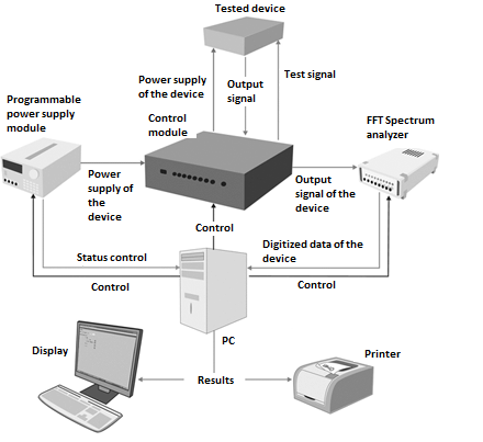
Figure 1. Diagram of hardware part of UTF VMG
The diagram shows that hardware part of unified test facility of virtual measure gauges consists of the following functional units:
Programmable power supply
Programmable power supply is designed for power supply for the product under test. The selection of power source is based on its specifications and requirements for supply of the product, which parameters are tested. As a rule, these requirements are listed in specifications. Functional characteristics of source are also important; they provide programming of the source through RS-232 interface at logging onto computer. This particular characteristic found use in SCADA-system of ZETVIEW, where special components are, performing operation of real device, and by extension such approach is convenient in automation of technical processes, in particular, for realization of power supply of device under test in UTF VMG.
ZET 017-U8 Spectrum analyzer
In order to measure output parameters of the product under test we need measurement device with corresponding metrological characteristics, as well as with the ability to communicate with SCADA-system ZETVIEW. We use multi-operated ZET 017-U8 spectrum analyzer that is designed for measurement of parameters of spectral composing signals, correlation signal structure, generation of electric signals with rated parameters. Analyzer connects to PC through USB 2.0 or Ethernet interface. Among other things, ZET 017 series spectrum analyzers are registered in the State Register of Measurement Devices under No.39236-08.
Using virtual devices based on ZET 017-U8, as a part of SCADA-system ZETVIEW, both measurement of output signals of amplifier with required accuracy, and generation of actuating signals, that relieves from furnishing of developed complex by separate device for signal generation can be performed.
Thus, ZET 017-U8 spectrum analyzer provides both forming of testing signals delivered to the input of product under test, as well as analysis of signal parameters received from output of product under test.
Monitoring panel
We need monitoring panel to ensure creation of modes required for product testing. Monitoring panel of typical UTF VMG performs different functions:
- delivery of supply voltage form programmable power supply to the product;
- commutation of access and output nets of product, if it is necessary for testing algorithm;
- logging testing signals from the generator (output of spectrum analyzer) to the product output;
- connection of product nets being under test to the access ports of the spectrum analyzer.
- reception and conversion of telemetric information;
- load commutation etc.
To that end, monitoring panel may consist of:
- ZET 453 switching unit is device set on module ADC-DAC ZET 210. Unit consists of 16 annunciator relays, managed by digital output of module. The management is performed with the aid of component ZETVIEW «Switching unit». Module serves for creation of automatic facilities and working places.
- ADC-DAC ZET 210 module provides performance of switching unit. ZET 210 has digital port, outputs thereof conform to TTL 3.3 V standards, which is enough for relay switching of switching unit.
- ZET 220 module ADC-DAC and ZET 230 for delivery of timed test input to the product under test, as each device has 4 output channels for generation of electric signals with stated parameters.
- ZET 412 amplifier provides galvanic isolation. Amplifiers are powered through USB of PC or through external power supply +5 V that makes them truly versatile facility for building of computer measuring systems with applying ADC and DAC modules.
- device for reception of telemetric information of standard RS232, RS485 and others for further conversion and its delivery to PC.
- different types of electric loads for maximum commonality of product testing modes and normal job mode of end production unit [3].
Computer (base unit, keyboard, mouse, monitor and printer).
The scheme shows that the computer in said system performs all operation functions, in particular the operation of programmable power supply, spectrum analyzer and monitoring panel is performed through the computer. Electronic computing machine passes all the flow of digitized data from amplifier under test, and also displaying the results and printing. The computer is selected based on requirements for ZETVIEW and ZETLAB software usage.
All points of the complex are connected by interconnect cables in accordance with schematic structure of connections, shown in Figure 2.
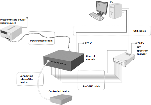
Figure 2. Schematic structure of UTF VMG
Alongside hardware part, we should also consider software part of the introduced facility. It is performed in the form of SCADA-project in ZETVIEW environment [2]. Functionally the program can be divided into 3 pages: «Main menu», «Debugging mode», «Testing mode».
Upon starting the project the user will see «Main menu» window, one of the variants of the window is shown in Figure 3. This window contains buttons of navigation into modes of testing and debugging of the product, and also entering information for report formation after testing of the product.
Figure 3. «Main menu» window
If operator will switch to a device debugging mode, he will see “Debugging mode” window, one of its variants is shown in Figure 4. The debugger has maximum options of the manual run of UTF VMG in order to create different modes, in particular to run programmable power supply source, switching units of monitoring panel etc. Using step-by-step guides, the debugger can find product problem in the shortest possible time and take measures to solve the problem.
Figure 4. «Debugging mode» window
If operator will switch to a device testing mode, he will see “Testing mode” window, its example is shown in Figure 5. You can perform product automatic test for conformity with the requirements and characteristics of the specifications. Each stated parameter is tested separately or general test of product is performed, according with results thereof report in the form of text document is issued.
Figure 5. «Debugging mode» window
One of the typical unified test facility of virtual measure gauges designed for serial product testing is shown in Figure 6.
Figure 6. Overview of typical ready-assembled UTF VMG
Unified test facility of virtual measure gauges is compact facility that is a favorably priced solution for large-scale enterprises aimed at carrying out technical conformance audit to determine whether the specified requirements have been met.
There are obvious advantages of the automated stand over manual equipment:
- automatic verification of test modes;
- embed protection functions during test;
- cutting test time of device;
- automatic generation of test report;
- convenient visualization of test results.
One of the main criteria in development of facility is the development of hardware and software product, the use thereof should not cause difficulties for average user, as there is an obvious focus on modularity in system building, as well as user-friendly interface of the software part.
The use of mentioned facilities improves the performance of technical control processes, and hence is a promising and advantageous solution when dealing with such industry issues as performance increasing and reducing the cost of test operations.
References:
1) https://zetlab.ru
2) Demkin V.I., Kabanova A.B., Kononov V.Yu., Shchagin A.V. Foundations of technological process automation. М.: Higher education, 2009.
3) Kester U. Analog-to-digital conversion. Translation from English. Edited by Volodina Ye.B. М.: Technosphere, 2007.