Researching Monomorphic Piezoceramic Cells For Converters
Collecting AFR from monomorphic piezoceramic cells for converters
Industry produces a considerable number of standard piezoceramic cells of different materials. The monomorphic piezoceramic cells are cells consisting of one piezoelectric cell. Surface of piezoelectric cells contains electrodes intended for connecting piezoelectric cells to electric circuit. Piezoelectric cells with two electrodes are called resonators.
To induce fluctuations, alternating voltage is supplied to resonator’s electrodes. When frequency of the supplied voltage matches natural frequency of the cell’s fluctuations, electromechanical resonance takes place. Resonance is physically characterized by laying a number of semi-waves in the wave spreading direction. Actually, there are several types of interconnected fluctuations in the resonator, generating interference to fluctuations in the main direction; therefore it is necessary to provide conditions when one type of fluctuations essentially prevails. Piezoelectric cell can produce different types of fluctuations: dilatational, thickness fluctuations, radial, torsion, bending, displacement.
Resonance frequencies of the most popular resonators are determined by formulas:
- for dilatational fluctuations:

- for thickness deviation fluctuations:

- for radial fluctuations:

where Y – Young`s modulus; ρ – density of piezoelement material, δ – Poisson`s ratio, n – harmonic number; l, a, r – length, thickness, radius of a piezoelement; zn – parameter defined through Bessel`s functions.
In practice, to define resonance frequency of dilatational fluctuations, an approximate formula is used:
![]()
where c – sound speed in the piezoelement’s material, l –resonance size.
Resonance frequency of radial fluctuations of disc:
![]()
Type of quartz resonator’s fluctuations depends on a cut. To generate dilatational fluctuations, x-cuts are used, for transverse-deviation fluctuations АТ- and VG-cuts are used.
Excitation of piezoceramic resonators depends on polarization direction. In rectangular piezoelements with electrodes on facets perpendicular to polarization direction, dilatational and transversal fluctuations can be induced according to dimensions. If polarization vector is parallel to the electrode plane, when a piezoelement energizes at a specified frequency, deviation fluctuations appear. The type of resonator fluctuations also depends on location and dimensions of electrodes. If electrodes are applied along the length of piezoelement, electric field generates the same sign mechanical stresses along entire length of the piezoelement. It is contributing to basic fluctuations on first harmonic and some weaker fluctuations on the third, the fifth, and the higher harmonics. If electrodes are applied on a half of length of piezoelement, it creates more favorable conditions for generating fluctuations on the second harmonic, since in this case the mechanical voltages at halves of length of the piezoelement can have different signs. Fluctuations can be induced in the piezoceramical resonator on the second harmonic even with solid electrodes, if separate sections of the piezoelement are polarized in opposite directions.
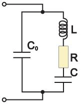
Excitation of a piezoelectric cell at resonance frequency produces variable charges on its electrodes, and quantity and phase of these charges are defined by amplitude and phase of piezoelement mechanical fluctuations and respectively external exciting voltage through it. There is a resonance dependence of piezoelectric cell resistance on exciting voltage frequency. It allows to regard a piezoelectric cell in a resonance region as an electric circuit (Figure 1) consisting of static capacitance C0, dynamic inductance L and capacitance C, active loss resistance R.
 Figure 1 |
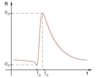
 Figure 2 |
As a series-parallel loop, this loop has two resonance frequencies: sequential resonance frequency fp and parallel resonance frequency (fa), i.e. anti-resonance. Resistance of piezoelectric resonator at resonance frequency (Rp) is the smallest and at anti-resonance frequency (Ra) is the largest and active (Figure 2).
For a piezoelectric resonator with solid electrodes, resonant and antiresonant frequencies can be expressed through parameters of equivalent circuit:
![]()
To determine quality of piezoelectric resonator, the following expression is used:
![]()
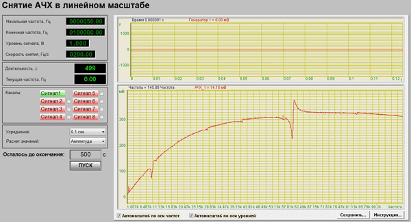
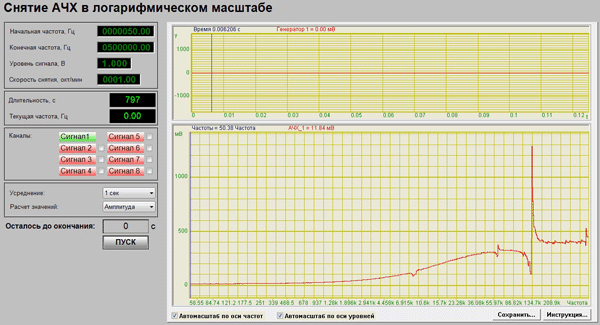
Resonance and anti-resonance frequency can be found with AFR indications on piezoceramic cell in sufficiently wide frequency range, and then some arithmetic calculations will help calculate parameters of piezoelectric resonator such as L, C and Q. ZETView SCADA system provides a ready-made solution to solve this kind of tasks in form of projects for reading AFR in a wide range of frequencies with possibility to add private calculation algorithms of different parameters (Figures 3 and 4 —”Reading AFR in linear scale” and “Reading AFR in logarithmical scale” projects).

Figure 3

Figure 4
This solution is suitable for production of quick, high-quality and low cost control of production. Since an automated bench for measuring piezoceramic cells parameters does not occupy much space and requires elementary PC skills only for operation, it is a profitable purchase for a plant.
Author: A. Antonov
References: “Piezoelectrical sensors” Sharapov V. M, Musiyenko M.P., Sharapova E.V.


