Vector Vibration Accelerometers Application Features
Description of the vector (triaxial accelerometer with one sensing element) vibration accelerometer. Sensor test results at industrial facilities are presented: aircraft engine AI-9V – (Professor N.Ye. Zhukovsky Military Engineering Academy), supports of the -250/300-240 turbine unit Т (Mosenergo ТPP-23), as well as when balancing a rotor of gas turbine energy plant GT-100-3 of 100 MW (Mosenergo SDPP-3).
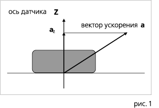
For determining vibration modes of different machines and mechanisms, piezoelectric one-component vibration accelerometers are used (Fig. 1).
These sensors help measure only projection of a vibration acceleration vector on the sensor axis. But this single projection does not allow to define neither size nor direction of the vibration acceleration vector a. To solve this problem, a triaxial sensor rather than a one-component sensor is required. And then, by three projections of a vector it is possible to determine its size and direction in the coordinate system. But all known triaxial vibration accelerometers represent a combination of three one-component sensors in one body. Since at the same time the sensing elements are inevitably located in three different points of space, i.e. because there are three measuring points with no coinciding coordinates, physical laws forbid to consider their readings as projections of vibration acceleration vector. However, this circumstance is ignored, which naturally distorts the information about vibration level of airplanes, helicopters, turbines of power plants, etc., at control points.
The fundamental difference of the proposed sensor is that it has only one sensing element (i.e. there is only one measuring point) in form of a rectangular block made from piezocrystal of a certain symmetry and 1.2 orientation.
The principle of sensor operation is shown on Figure 2.
If the vector or vibration acceleration is directed along Z axis, the charges appear only on facets perpendicular to Z axis; if the vector or vibration acceleration is directed along Y axis, the charges appear only on facets perpendicular to Y axis. And finally if the vector a is directed along X axis, the charges appear only on facets perpendicular to X axis. In each of these three cases, the remaining four facets will have no charges at all which results from the symmetry theory and tensor analysis. Thus, theoretically the transverse sensitivity of sensor must be equal to zero what can be illustrated in form of a matrix:
| vibration | |||||
| X | Y | Z | % | ||
| Output signal | X | 100 | 0 | 0 | |
| Y | 0 | 100 | 0 | ||
| Z | 0 | 0 | 100 | ||
Actually it corresponds to general requirements (<5%). The quality of the sensors in question depends on the quality of piezoelectric cell, cable, glue, jacks and structure. But even though the domestic components are used, the characteristics of sensors exceed those of sensors made by Brüel & Kjær, type 4506, and by Endevko, type 2228S (see table).
| Technical parameters | Vector accelerometer type VTK3 | Brüel & Kjær type 4506 Endevko type 2228C | Endevko type 2228C |
| Number of measured axes | 3 | 3 | 3 |
| Number of piezoelectric cells | 1 | 1 | 3 |
| Basic sensitivity (sensor+amplifier), mV/g | 100 | 100 | — |
| Maximum transverse sensitivity, % | 5 | 5 | 5 |
| Resonance frequency along Z axis, kHz | 58 | 10 | 21 |
| Frequency range (5%), Hz | 5 to 15,000 | ||
| Frequency range (±5%), Hz | 20 to 4,000 | ||
| Frequency range (±10%), Hz | 1 to 2000 | ||
| Temperature range, °C | —60 to +250 | —54 to +121 | —55 to +175 |
| Temperature sensitivity coefficient | 0.05%/°С | 1м•c-2/°С | 0.2%/°С |
| Dimensions, mm | O22×26 | 17×17×14,5 | — |
| Weight without cable, g | 27 | 15 | 15 |
But the main difference of vector sensor from similar well-known products is not that some parameters are better and the other are worse, but that it is the only one that has a single measuring point, which allows receiving the value and the direction of vibration acceleration vector in this point by three projections. Therefore, only new generation sensor allows receiving reliable information about vibration modes of different machines and mechanisms. When using any other sensors, the relation between mechanical vibration parameters and electric signals of vibration measuring system is hard to estimate.
The sensor operates together with three-channel charge amplifier, which has a symmetric (differential) high-resistance input and an asymmetric low-resistance output. The amplifier is delivered with DC power unit + 15 VDC.
There have been performed comparative tests of standard one-component sensor (type АВС-117, No. 81182604, manufacturer “Biofizpribor”, Lviv), and triaxial sensor (type VTK3, No. 002, manufacturer “REM-vibro”, Noginsk) on the aircraft engine in real conditions (type AI-9V).
Figure 3 shows results of vibration test in one of many engine modes (frequency range 10 to 600 Hz)
Projections of vibration (vibration acceleration m/s2, RMS) X direction (sensor 002), Y direction (sensor 002), Z direction (sensors 002 and АВС-117) Figure 3
A one-component sensor was installed on the engine parallel to Z axis of a triaxial sensor, and their indications matched (1.5g). But along the X axis of the triaxial sensor acceleration was 5g and 5.5g along the Y axis. Thus, true value of vibration acceleration measured with vector sensor was 7.6g. And it is with simultaneous reading of standard sensor 1.5g, i.e. the standard sensor in this particular experiment showed indications 5 times lower than true value.
Thus, the vibration tests on the aircraft engine confirmed that use of one-component sensors leads to understated indications of a true vibration acceleration vector.
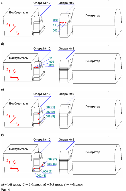
During measurement of vibration parameters of the supports of turbine unit Т-250/300-240, the vector sensors (No. 002 and No. 008) and one-component sensors (No. 09,10,11,15 made by Kodis, Voronezh) were used. The measurements of vibration parameters were carried out with a purpose to determine contour characteristics of constructions and shapes of fluctuations at standard control points of absolute vibration and in other points according to the test program.
Based on the test results, the following vibration characteristics were determined:
- Total vibration speed, RMS (mm/s);
- Amplitude of the reverse harmonic (effective value of vibration speed in mm/s and range of vibration relocation in µm);
- Phase of reverse harmonic (degrees);
- Spectral characteristics of vibration in range from 10 to 1,000 Hz (vibration speed in mm/s).
The sensor positions are shown on Figures 4а,b,c,d.
Spatial distribution of displacement vector depending on phase relations of space vibration measured in a three-dimensional coordinate system was first practically obtained, as shown on Fig. 5.
| Point number | Three-dimensional motion path with projections, µm | Point number | Three-dimensional motion path with projections, µm |
| 1 | 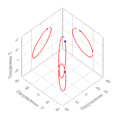 |
4 | 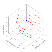 |
| 2 | 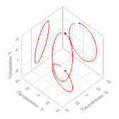 |
5 | 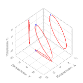 |
| 3 | 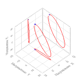 |
6 | 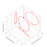 |
in points 1-3 vertically (cycle No. 3) in points 4-6 horizontally (cycle No. 4) Figure 5
Based on the test results described in detail in 3, the following conclusions are made:
- The indications of one-component and vector sensors along corresponding axes are matching very accurately. At the same time, the values of components of space vibration acceleration vector along other axes significantly change a view of magnitude and vector direction.
- The single sensing element of vector sensors excludes phase distortions on three axes. This fact enables a new approach to the methodology of balancing works, particularly in cases where high degree of balance is required. Application of vector sensors enables to increase the number of used adjustment planes threefold, thus significantly improving balancing precision,as well as to provide a more even distribution of adjusting masses along the rotor axis. Application of vector sensors in power engineering allows to evaluate real vibration states of energy constructions, helps to discover causes of increased vibrations (pullout of supports, resonances and increased flexibilities of supporting elements, loosening of mountings…).
- Application of vector sensors enables to obtain reliable “vibration portraits” of explored aggregates and structures and reveals a substantially new layer of vibration monitoring and diagnostics of facilities exposed to vibration destruction.
Balancing of six-support shaft line of energy gas turbine plant GT-100-3 is carried out using two planes of imbalance adjustment. This operation includes determination of total dynamic ratios of influence and their use during calculations of adjusting masses. As a result of balancing within one iteration, initial vibration of supports was reduced 2.5 times in all the directions of measurement to the level significantly lower than allowed by PTE for long-term operation, which excluded the need of corrective starts. Each corrective start according to the professionals is evaluated at RUB 500 000-800 000.
SUMMARY:
- Use of one-component vibration sensors gives 3-5 times undervaluation against a true value of vibration parameters.
- Use of triaxial sensors significantly reduces the range of operating frequencies (not higher than 2-4 kHz).
- Only vector sensors enable to obtain accurate size and direction of vibration acceleration vector.
- Only vector sensors can lead to justified extension of MTBF of energy equipment in various industry branches.
- Only vector sensors enables timely prevention of technology-related disasters.
REFERENCES:
- RF Patent No. 2061242, Triaxial piezoelectric vibration accelerometer with one sensing element.
- I.B. Kobyakov, Triaxial vibration accelerometer for systems of vibration diagnostics of technical systems, “Control. Diagnostics”, No. 10(40) 2001, p. 17-18.
- A.I. Kumenko, S.V. Kalinin, I.B. Kobyakov, Vibration tests of turbine unit supports with new generation triaxial vibration accelerometers, “Teploenergetika”, No. 6, 2003, p. 36-43..
Technical Specifications Of Sensors And Amplifiers
Vector Vibration Accelerometer Type VTK 1
delivered with three-channel electric charge amplifier UTK 2
| # | Technical specifications | Axes | ||
| X | Y | Z | ||
| 1. | Measurement range of vibration accelerations (RMS), ms-2 | 0.5 to 1,400 | 0.5 to 1,400 | 0.5 to 1,400 |
| 2. | Frequency range (5 %), Hz | 5 to 5,000 | 5 to 5,000 | 5 to 10,000 |
| 3. | Rated value of the conversion ratio at basic frequency of 40 Hz,
pC / ms-2 mV / ms-2 |
0.3
0.7 |
0.3
0.7 |
1.0
2.0 |
| 4. | Valid conversion coefficient at 40 Hz basic frequency, mV/ms-2 | 1.0 to 10.0 | 1.0 to 10.0 | 1.0 to 10.0 |
| 5. | Error of valid conversion coefficient at 40 Hz basic frequency, %, up to | ±5 | ±5 | ±5 |
| 6. | Maximum nondestructive shock value, g | 2,000 | ||
| 7. | Maximum relative coefficient of the transverse conversion at 40 Hz basic frequency, % | 5.0 | 5.0 | 5.0 |
| 8. | Intrinsic noise level, mV, up to | 20 | 20 | 20 |
| 9. | Resonance frequency of mounted sensor, kHz | 27 | 34 | 38 |
| 10. | Amplitude non-linearity at 40 Hz basic frequency, % | 1 | 1 | 1 |
| 11. | Operating temperature range, 0C accelerometer amplifier | — 60+ 250
-20+ 70 |
— 60+ 250
-20+ 70 |
— 60+ 250
-20+ 70 |
| 12. | Additional error caused by change of ambient temperature %/ °C, up to | 0.1 | 0.1 | 0.1 |
| 13. | Coefficient of deformation influence on 10-6 relative deformation units, m/s2, up to | 0.03 | 0.03 | 0.03 |
| 14. | Sensor capacity, pF | 410 | 410 | 530 |
| 15. | Insulation resistance at 20 °C, Ohm | 1013 | 1013 | 1013 |
| 16. | Dimensions, mm | O22×25 | ||
| 17. | Sensor weight (without cable), g | 27 | ||
| 18. | Piezoelectric material | type 850, APC | ||
| 19. | Body material | Titanium | ||
| 20. | Mounting mode | 4*М5 pins | ||
Vector Vibration Accelerometer Type VTK 3
delivered with three-channel electric charge amplifier UTK 2
| # | Technical specifications | Axes | ||
| X | Y | Z | ||
| 1. | Measurement range of vibration accelerations (RMS), ms-2 | 0.5 to 1,400 | 0.5 to 1,400 | 0.5 to 1,400 |
| 2. | Frequency range (5 %), Hz | 5 to 7,000 | 5 to 7,000 | 5 to 20,000 |
| 3. | Rated conversion coefficient at 40 Hz basic frequency,
pC / ms-2 mV / ms-2 |
0.3
0.7 |
0.3
0.7 |
1.0
2.0 |
| 4. | Valid conversion coefficient at 40 Hz basic frequency, mV/ms-2 | 1.0 …… 10.0 | 1.0 …… 10.0 | 1.0 …… 10.0 |
| 5. | Error of valid conversion coefficient at 40 Hz basic frequency, %, up to | ±5 | ±5 | ±5 |
| 6. | Maximum nondestructive blow, g | 2,000 | ||
| 7. | Maximum relative coefficient of transverse conversion at 40 Hz basic frequency, % | 5.0 | 5.0 | 5.0 |
| 8. | Self-noise level, mV, up to | 20 | 20 | 20 |
| 9. | Resonance frequency of mounted sensor, kHz | 20 | 20 | 52 |
| 10. | Amplitude non-linearity at 40 Hz basic frequency, % | 1 | 1 | 1 |
| 11. | Operating temperature range, 0C accelerometer amplifier | — 60+ 250
-20+ 70 |
— 60+ 250
-20+ 70 |
— 60+ 250
-20+ 70 |
| 12. | Additional error caused by change of ambient temperature %/ °C, up to | 0.1 | 0.1 | 0.1 |
| 13. | Coefficient of deformation influence on 10-6 relative deformation units, m/s2, up to | 0.03 | 0.03 | 0.03 |
| 14. | Sensor capacity, pF | 410 | 410 | 530 |
| 15. | Insulation resistance at 20 °C, Ohm | 1013 | 1013 | 1013 |
| 16. | Dimensions, mm | O22×26 | ||
| 17. | Sensor weight (without cable), g | 27 | ||
| 18. | Piezoelectric material | type 850, APC | ||
| 19. | Body material | Titanium | ||
| 20. | Mounting mode | М5 pin | ||
Vector Vibration Accelerometer Type VTK 3
delivered with three-channel electric charge amplifier UTK 2
—
5 to 20,000 — 31.3
| # | Technical specifications | AXES | ||
| X | Y | Z | ||
| 1. | Measurement range of vibration accelerations (RMS), ms-2 | 0.5 to 1,400 | 0.5 to 1,400 | 0.5 to 1,400 |
| 2. | Frequency range (5 %), Hz | — | ||
| 3. | Rated conversion coefficient at 40 Hz basic frequency,
pC / ms-2 mV / ms-2 |
0.3
0.7 |
0.3
0.7 |
1.0
2.0 |
| 4. | Valid conversion coefficient at 40 Hz basic frequency, mV/ms-2 | 1.0 to 10.0 | 1.0 to 10.0 | 1.0 to 10.0 |
| 5. | Error of valid conversion coefficient at 40 Hz basic frequency, %, up to | ±5 | ±5 | ±5 |
| 6. | Maximum nondestructive blow, g | 2,000 | ||
| 7. | Maximum relative coefficient of transverse conversion at 40 Hz basic frequency, % | 5.0 | 5.0 | 5.0 |
| 8. | Self-noise level, mV, up to | 20 | 20 | 20 |
| 9. | Resonance frequency of mounted sensor, kHz | — | ||
| 10. | Amplitude non-linearity at 40 Hz basic frequency, % | 1 | 1 | 1 |
| 11. | Operating temperature range, 0C accelerometer amplifier | — 60+ 250
-20+ 70 |
— 60+ 250
-20+ 70 |
— 60+ 250
-20+ 70 |
| 12. | Additional error caused by change of ambient temperature %/ °C, up to | 0.1 | 0.1 | 0.1 |
| 13. | Coefficient of deformation influence on 10-6 relative deformation units, m/s2, up to | 0.03 | 0.03 | 0.03 |
| 14. | Sensor capacity, pF | 380 | 380 | 500 |
| 15. | Insulation resistance at 20 °C, Ohm | 1013 | 1013 | 1013 |
| 16. | Dimensions, mm | O38×28 | ||
| 17. | Sensor weight (without cable), g | 39 | ||
| 18. | Piezoelectric material | Pz 27 | ||
| 19. | Body material | Titanium | ||
| 20. | Mounting mode | 3*М4 pins | ||
Источник: www.vsvm.ru

