
Impact of External Factors
And Instructions on Operating Vibration Sensors and Accelerometers
For correct operation and measurements consider the following external factors and follow the operation instructions:
- effect of ambient temperature;
- effect of variable magnetic field;
- acoustic sensitivity;
- effect of test object deformation;
- transverse sensitivity;
- cable effect;
- effect of ground loops;
- dislocation of zero line;
- requirement for power supply of vibration transducers with built-in electronics.
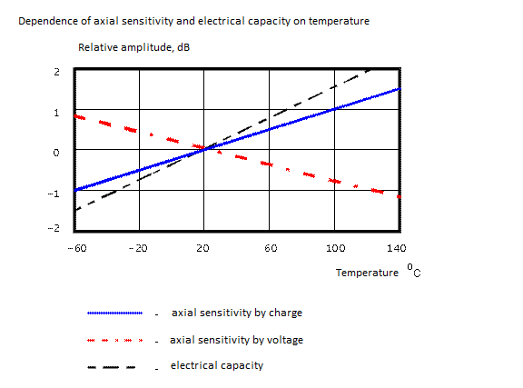
Effect of Ambient Temperature
The accelerometers operate in wide temperature range. When temperature deviates from normal range, axial sensitivity and electric capacity of vibration transducers change. These changes are reversible and recover as the temperature level is restored.
The temperature dependencies of sensitivity and capacity typical for the accelerometer are shown below.
Effect of Variable Magnetic Field
It is very difficult to determine sensitivity of accelerometers to magnetic fields precisely.
Magnetic susceptibility of the key construction materials plays the key role in determining sensitivity of the accelerometer to variable magnetic field. Therefore, the key construction elements of the vibration converters are made of non-ferromagnetic materials with magnetic susceptibility close to zero. Sensitivity of VS vibration transducers to variable magnetic field does not exceed 10-5 g/A·m-1, and its effect is noticeable only during the measurement of low level accelerations.
Acoustic Sensitivity of Accelerometers
Acoustic sensitivity of accelerometers is a very complex task associated with exception of mechanical impact of acoustic field sources. To conduct such researches, acoustic chamber with high sound pressure level is used. The accelerometer under test is placed into such chamber. The device guarantees minimum transfer of mechanical force and mechanical fluctuations to the accelerometer inside of the chamber.
The electric signal generated by the accelerometer is amplified and formed by a corresponding preamplifier, and then sent to FFT spectrum analyzer. The sound field source is powered by the FFT spectrum analyzer generator. A linear-frequency-modulated signal, i.e. a sinusoidal signal with constantly increasing frequency, is set at the generator. Based on the frequency analysis of accelerometer signal (correlational and mutually spectral analysis with a programmable delay line), it is possible to identify components corresponding to acoustic effect on the accelerometer. The signal analysis uses the fact that speed of sound in the air and velocity of vibration spreading among the acoustic camera elements are different, and it means different delays of signals of different nature.
High pressure acoustic fields have insignificant impact on the output signal of VS vibration transducers. At sound pressure levels around 140 dB at 250 Hz, acoustic sensitivity of VS vibration transducers is deciles of “g”.
Effect of Test Object Deformation
During installation of vibration transducers on a surface heavily deforming during a blow or vibration, a spurious signal may appear due to transfer of deformation through the body base to the sensing element.
The VS vibration transducers have low deformation sensitivity, which does not exceed 5·10-4 300 g/m·µm at 300 µm/m deformation.

- Transverse Sensitivity The transverse sensitivity of VS vibration transducers does not exceed 5% of axial sensitivity. Datasheet for each vibration transducer contains only a maximum value of the transverse sensitivity. To reduce impact of the transverse sensitivity on measurement results, it’s required to align the expected direction of acceleration to operating axis of sensitivity of the vibration transducer. The optimal deviation from acceleration direction to the operating axis of sensitivity is within ±15°.
- Cable EffectUse of unreliable connection cables, improper wiring and unreliable mounting can lead to significant increase of errors in mechanical fluctuation measurements with the accelerometers and FFT spectrum analyzers.The main reasons are:
- Dynamic bending, compression and stretch of coaxial cable can lead to local loose contact between shield and dielectric. The local changes of capacitance arising therefrom lead to spurious electric charge. This effect called triboelectric effect causes difficulties in researching mechanical fluctuation, especially those with small amplitudes.
- Intensive electromagnetic interferences can cause spurious electric voltage in the form of noise overlaid on the signal.
Mechanical fluctuations of unreliably fixed connection cable can lead to undesirable effect of curving force on piezoelectric accelerometer cells connected to output jack and therefore to spurious electric signal. The interference is severe when using the accelerometers which contain piezoelectric cells operating at compression.

Application of special low noise coaxial cables minimizes triboelectric noise.
Even when using the anti-vibration low-noise cable during the low level accelerations measurements (“g” units), effects associated with triboelectric phenomena in the cable can still appear. During impact loading this effect is proportional to length of the cable’s fluctuating part (unrestrained) and duration of impact loading. With impact loading duration up to 10-20 ms, its effect on measurement results is insignificant. At the same time, at low frequency fluctuations the effect of triboelectricity on measurement results can be crucial. Therefore, during measurement of low level acceleration using piezoelectric vibration transducers, it is reasonable to:
- decrease length of cable areas exposed to vibration or impact perturbances;
- decrease length of a cable section located between the last point of its fastening on a mobile object and first fixed point (Figure 1);
- mount a cable on a subject under tests without tension and bending using cable ties, staples, mastics, etc., with 200–300 mm interval and the first mounting point 30-50 mm away from the vibration transducer;
- before the test (if possible), determine the signal level depending on triboelectricity in cable lines. The vibration transducer is a recording equipment that utilizes “background” communication lines during the tests (or background vibration transducers).
Effect of Ground Loops
Measurement of accelerations by vibration transducers may be rather difficult due to electric loops caused by improper grounding of the object under test and matching equipment. At the same time, additional voltage which is added to the output signal of vibration transducer can significantly distort the measurement results at low levels of measured accelerations. Grounding of the object under test with installed vibration transducers and equipment in the same point is the necessary requirement to prevent ground loops. Grounding on recording equipment is preferable.
Grounding of Object and Equipment
а) wrong;
b) correct
Figures: 1 — object under test; 2, 3 — matching and recording equipment; 4 — electrical insulation.
Dislocation of Zero Line
Dislocation of zero line in vibration transducers can take the form of dislocation of permanent component which returns to zero line exponentially.
The causes of zero line dislocation can include cable effect, improper ground of the object under test and recording equipment, as well as design features of vibration transducers.
The vibration transducers with sensing element working in shear are minimally affected by zero line dislocation and therefore surpass the vibration transducers with other structure.