
Strain Gauge Measurements
The choice of a primary transducer is crucial for any task in computer automation of measurements, testing and control of technological production. The primary converters of external impact signals into an electric signal are based on different physical effects and have different types and designs. Let us consider one of the common transducer types – resistive transducers.
Resistive sensors are widely used in tensometry. Tensometry (Lat. tensus – stressed, tense and Gr. metréō – measure) (strain gauge measurement) implies experimental determination of stress state of structures based on the measurement of local strains. Mechanical strain of material changes its electric resistance. This effect is called tensoresistance. This effect is a basis for strain gauge sensors, which respond to mechanical stress σ:
![]()
where E is Young’s modulus of the material, F is the applied force, dl/l = e – relative strain of the material.
Strain gauge measurements are conducted using ZET 7010 Tensometer-485, ZET 7110 Tensometer-CAN, ZET 7111 Tensometer-CAN measuring modules, or ZET 017-T8 strain gauge module with Strain Gauge Sensor software facility. The strain gauge sensors or resistive strain sensors of different design can serve as sensing elements. Tensoresistance is utilized for measuring various physical values: weight, pressure, mechanical stress, etc. Figure 1 shows the shapes of measuring grids of resistive strain sensors manufactured by Messtechnik HBM. Figure 2 shows a typical pressure sensor manufactured by Metronik LLC.
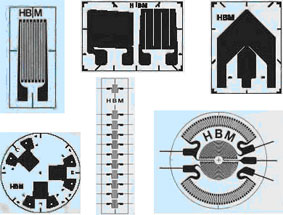
Figure 1
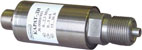
Figure 2
For building the multi-channel control and measuring systems of process automation, several ZET 017-T8 strain gauge modules are used, facilitating the establishment of up to 128 measuring channels. For connecting so many sensors, the terminal modules are applied (Figures 3 and 4). The modules can be installed on a DIN bar in order to integrate the strain gauge measuring system into the existing process. For building a distributed strain gauge measuring system, ZET 7010 Tensometer-485, ZET 7110 Tensometer-CAN, ZET 7111 Tensometer-CAN modules are utilized.
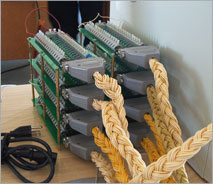
Figure 3
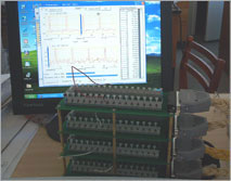
Figure 4
The digital input/output of ZET 017-T8 strain gauge module or the control module ZET 7060 Digital-485 or ZET 7160 Digital-CAN is used to monitor and manage processes. For example, when the pressure at a monitored point of the analyzed object is exceeded, the digital output transmits a signal to the actuator, which triggers it to, for example, open the bleed valve. Once the pressure is back to normal, the digital output signal turns off and the system continues to run normally. Thresholds (setpoints) of digital input/output trigger are set by the operator. The measured parameters control and trigger algorithms of setpoints may vary. The whole process of parameter measurements, setpoint triggering, and occurrence of irregular situations is displayed on the screen in real time and logged for further analysis and storage.
See also
- Theory of Strain Gauge Measurements, Layouts of Resistive Strain Sensor Connection to ZETSENSOR
- Layouts of Resistive Strain Sensor Connection to ZET 017-T8 Strain Gauge Module
- DIY Strain Gauge Weigher
- Establishment of Strain Gauge Bridge Circuits for Measuring Various Parameters
- Application of Resistive Strain Sensors for Measurement of Physical Values
- ZET 7010 Tensometer-485, a smart strain gauge sensor with RS-485 interface (static measurements)
- ZET 7110 Tensometer-CAN, a smart strain gauge sensor with CAN interface (static measurements)
- ZET 7111 Tensometer-CAN, a smart strain gauge sensor with CAN interface for dynamic measurements