Strain Gauge Bridge Testing
This section addresses the issue of strain gauge bridge testing.
To test the operation capacity of a strain gauge bridge, make sure that all the resistive strain sensors are functioning properly and the circuit is powered.
Testing without load
 In order to test the operability of all resistive strain sensors of the strain gauge bridge, the resistance of diagonals and sides of circuit shall be tested without any load.
Let us consider a case with 200 Ohm resistance of R1, R2, R3, and R4 resistive strain sensors. In this case:
- the resistance of diagonals (i.e. resistance between points 1 and 3 and between points 2 and 4) shall be 200 Ohm,
- the resistance of sides (i.e. resistance between pairs of points 1-2, 2-3, 3-4, 4-1) shall be 150 Ohm (i.e. 3/4 of 200 Ohm).
Load Testing
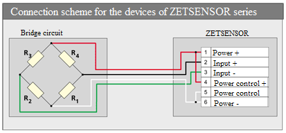
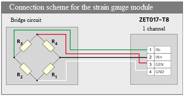
The circuit shall be powered, for example, from ZET 017-T8 strain gauge module or ZET 7010 or ZET 7110 module with DC voltage of U V.
- Measure the power voltage between GND and GEN points in case of connection to strain gauge module, and between Power+ and Power- in the case of connection to ZETSENSOR module. It shall be U V.
- Measure the voltage between GND and IN+ points in case of connection to strain gauge module, and between Input+ and Power- in case of connection to ZETSENSOR module. It shall be 0.5×U V.
- Measure the voltage between GND and IN- points in case of connection to a strain gauge module, and between Input- and Power- in case of connection to ZETSENSOR module. It shall be 0.5×U V.