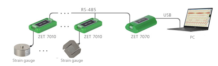
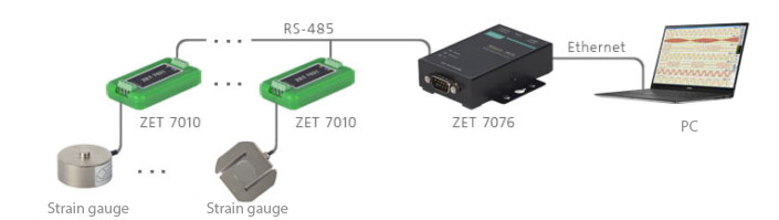
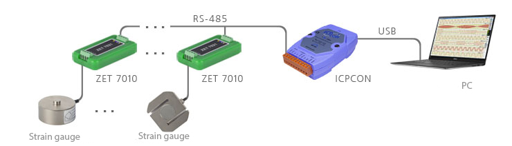
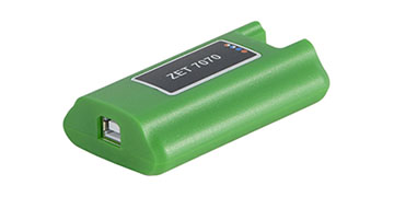
ZET 7010 Strain gauge sensor


- RS-485 data interface
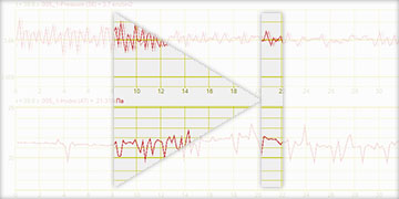
- Statical measurements perfomance
- Explosion-proof product version available*
POR (price on request)
Digital strain gauge sensors ZET 7010 in industrial version having explosion-proof mark are supplied upon special request and for additional cost.
Specifications
of digital strain gauge sensors ZET 7010
| Metrological specifications | |
|---|---|
| Measured value | deformation, strain, torque, power |
| Voltage measuring range from connected primary transducers | from -6 to +6 mV/V |
| Common-mode voltage range | 0 to 4,5 V |
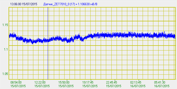
| Sensitivity threshold (minimum difference value between two consequtively measured values) | 0,0001 mV/V |
| Absolute measuring tolerance (from the upper measuring range limit) | 0,05 % |
| Relative measuring tolerance (from the measured value) | 0,05 % |
| Additional measuring tolerance (depending on temperature changes) | 0,05 %/10°C |
| Technical specification | |
| Type of connected sensors | power sensor, bridge / half-bridge circuit strain sensors (resistive strain sensors) |
| DC to the primary transducer | 4,2 ± 0,2 V |
| Maximum current to the primary transducer | 25 ± 1,5 mA |
| Refresh rate | 1 Hz |
| Data interface | RS-485 |
| Data rate | 4800, 9600, 14400, 19200, 38400, 57600, 115200 bit/s |
| Parity control | 0 – no control; 1 – control (oddity, ODD) |
| Data communication protocol | Modbus RTU |
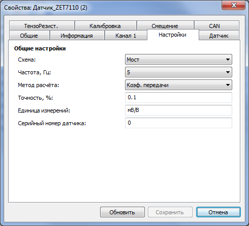
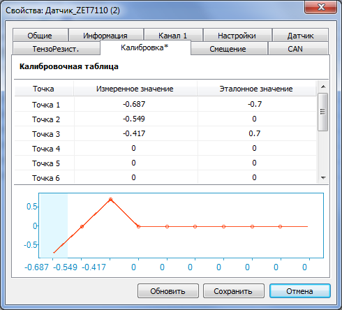
| Calculation method | input data is transmitted into resultant or, according to linear law with tilt set as transfer ratio or, according to piecewise linear law as per calibration table |
| Operational characteristics | |
| Dimensions | 71×39×17 mm |
| Weight | 30 gr |
| Device power | 9 to 24 V |
| Power consumption (without primary transducer) | 0,5 W |
| Polarity reversal protection | yes |
| Operation temperature range | -40 to +100 °C |
| Electromagnetic compatibility EMC | |
| MEK 61000-4-2 (IEC 61000-4-2), ESD | contact 4 kV, air 8 kV |
| MEK 61000-4-4 (IEC 61000-4-4), EFT | power 0,5 kV, signal 0,25 kV |
| MEK 61000-4-5 (IEC 61000-4-5), Surge | 500 V |
Parity control is not supported in the mode EVEN. Modbus ASCII – not supported.