
STEPPER MOTOR CONTROL SYSTEM
The process automation keeps gaining importance nowadays. To ensure that, control signals have to be converted into mechanical movements. One method for this is the use of stepper motors.
A stepper motor is an electromechanical device which converts electric impulses into discrete mechanical movements
Advantages of stepper motors
- rotor rotation angle is determined by the number of impulses fed to the engine;
- if the windings are energized, then the engine provides the full torque in a pause mode;
- good stepper motors ensure 3-5% of the step accuracy, and there is no error accumulation between steps;
- possibility of fast start/stop/reverse;
- high reliability due to the absence of the brushes, a stepper motor service life is, in fact, determined by the bearings service life;
- precise dependence of the position on the input impulses ensures positioning without any feedback;
- possibility of very low rotation speeds for a load attached directly to the engine shaft, without an intermediary reducer;
- wide speed range can be covered, the speed is proportinate to the input impulses frequency;
Disadvantages of stepper motors
- resonance phenomenon is found in stepper motors;
- due to operation without any feedback, position control may be lost, so it is recommended to complete the stepper motor control systems with an encoder;
- power consumption is not decreased even without any load;
- high-speed operation is complicated;
- low specific power;
- comparatively complex control system.
Application scope of stepper motor
- drives of coordinate worktables and manipulators axes;
- linear travel systems;
- packing and conveyor equipment;
- equipment for textile and food industries;
- printing equipment;
- feed, dosing devices;
- welding machines.
Operating principle of stepper motor
The main principle of stepper motor operation is as follows: a two-pole electric engine rotor made of special magnetically soft steel is placed on a four-pole stator. The first pole pair is made of magnets (permanent), and the second pair has a step electric engine control winding. While there is no current in the windings, the engine rotor is positioned along the magnets and is held stable with some force (which depends on the magnetic flux strength).
As soon as the voltage (DC) is supplied to the step electric engine control winding, the magnetic flux exceeding the magnetic flux of the existing permanent magnets appears. Under the electromagnetic impact the rotor starts changing the angle trying to come to a position which is uniaxial with the control winding poles. The next control impulse turns off the electric voltage on the control winding completely. As a result, the engine rotor is moving under the impact of the magnets magnetic flux.
This document describes the algorithm of two-phase (bipolar) and four-phase (unipolar) type stepper motor control using the stepper motor control unit with CAN interface, ZET 7160-S StepMotor-CAN, or with RS-485 interface, ZET 7060-S StepMotor-485.
Bi-polar (two-phase) stepper motor
The two-phase stepper motor (bipolar stepper motor) has one winding in each phase, which is to be reversed by the driver in order to change the magnetic field direction. The engine of this type requires a bridge driver or the half-bridge one with two-pole power supply. In total, the bipolar engine has two windings and, accordingly, four outputs.
 Fig. 1: Bipolar stepper motor internal circuitry |
 Fig. 2: Bipolar stepper motor output diagram |
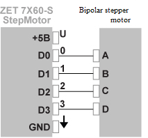 Fig. 3: Bipolar stepper motor connection to ZET 7X60-S diagram |
Unipolar (four-phase) stepper motor
A four-phase step engine (a unipolar stepper motor) also has one winding in each phase, but there is a branch from the middle of the winding. This allows for changing the direction of the magnetic field by simple switching of the winding halves. This simplifies the driver layout significantly. The driver has to have only 4 simple keys. Thus, another method of the magnetic field direction changing is used in the unipolar engine. The middle branches of the windings may be joined inside the engine, so this type of engine may have 5 or 6 outputs.
 Fig. 4: Unipolar stepper motor internal circuitry |
 Fig. 5: Unipolar stepper motor output diagram |
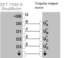 Fig. 6: Unipolar stepper motor connection to ZET 7X60-S diagram |
Operation modes of stepper motor
There are several methods to control the stepper motor phases. The most common of those are full-step and half-step modes. There also are operation modes with 1/4, 1/8, and 1/16 of the step. However, the above modes are required for a narrow range of tasks and they require a significant complication of the microcontroller circuit and the control algorithm. A sequence of generated impulses for different modes of the step engine operation is shown below; a unipolar engine has been taken as an example.
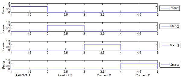
Fig. 7. Full-step mode with 1 active winding on each step
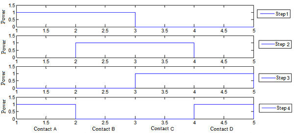
Fig. 8. Full-step mode with 2 active windings on each step
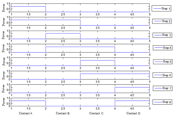
Fig. 9. Half-step mode
Stepper motor acceleration and deceleration
Such parameter of the stepper motor as the torque dependency on the speed is the most important one in selection of the engine type, selection of the phase control method, and selection of the driver circuitry. In design of high-speed drivers for stepper motors, it should be accounted for that the engine windings are inductive. This inductivity determines the time of the current build-up and fall. So, if a rectangular shape voltage is applied to the winding, the shape of the current will not be rectangular. At low speeds (Fig. 10a) the time of the current build-up and fall cannot influence the torque significantly , however, the torque decreases at high speeds. This is due to the fact that the current in the stepper motor windings at high speeds does not have enough time for reaching the maximum value (Fig. 10b).

Fig. 10. Stepper motor windings current dependency on the frequency
Thus, to operate a stepper motor at a high speed, it should be accelerated and then decelerated, otherwise the synchronism between the stepper motor and the controller will be lost, and the stepper motor rotor position will be displaced.
Stepper motor control using ZET 7X60-S StepMotor unit
Before working with a stepper motor, it is necessary to set the required parameters on the “Settings” tab.
- Sampling rate is the frequency of refreshing the information in the channel on the number of steps made.
- Engine type is the type of the engine connected to ZET 7X60-S StepMotor unit.
After that, using the “Control” tab, stepper motor control may be started.
- Start/Stop: start/stop the stepper motor rotation;
- Rotation direction: sets the step engine rotation direction, clockwise or counterclockwise;
- Number of steps before stopping: the number of steps the stepper motor will make after start;
Step time: the step engine rotation speed.
 Fig. 11. “Settings” tab in the MODBUS-ZELAB program |
 Fig. 12. “Control” tab in the MODBUS-ZELAB program |
When running the command, the controller depicts current number of steps performed at a rate set in the settings (Settings—>Sampling rate).

Fig. 13. Display of the number of steps in the “Multi-channel oscillograph” ZELAB program
Stepper motor with feedback control system
The stepper motor with feedback control system is built based on the ZET 7060-S StepMotor-485 (ZET 7160-S StepMotor-CAN) stepper motor control unit and ZET 7060-E Encoder-485 (ZET 7160-E Encoder-CAN) smart encoder. To connect to the ZELAB system, ZET 7070 interface converter is used. Stepper motor control is performed by signals feed from ZET 7060-S StepMotor-485 (ZET 7160-S StepMotor-CAN) unit. The stepper motor status control is performed by the encoder whose signal is processed by the ZET 7060-E Encoder-485 (ZET 7160-E Encoder-CAN) unit. Signals from the smart encoder are processed and software control of the ZET7060-S StepMotor-485 (ZET 7160-S StepMotor-CAN) unit is performed using the ZELAB program.
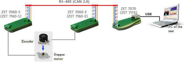
Layout of the stepper motor control system with feedback
Structure of the stepper motor control system with feedback
| Description |
| ZET 7060-S StepMotor-485 or ZET 7160-S StepMotor-CAN control unit A digital stepper motor control unit with RS-485 or CAN interface. |
| Angular travel sensor Angular travel conversion into a sequence of electric signals containing the information on the magnitude and direction of the travel. Body diameter: 50 mm. Resolution: up to 320,000 increments per revolution. |
| ZET 7060-E Encoder-485 or ZET 7160-E Encoder-CAN measuring unit Conversion of the sensor signal to the values of the angular travel and subsequent transmission of this data via the Modbus protocol through RS-485 or CAN 2.0 interface. |
| ZET 7070 RS-485↔USB or ZET 7174 CAN-USB A unit for data transmission from the measuring modules to the PC |
| MODBUS OPC Server “Smart sensor data server” program |
| Cables for connecting measuring and control modules to ZET 7070 or ZET 7174. |
| ZELAB software package Programs for displaying the measurement results of the smart sensors in the numeric and graphical form on the plane and in space. |
| SCADA ZETVIEW Graphical application development environment for measurement automation |