ZET 048 Seismic Impact Control System

Seismic impact control system is used to control ground surface shifts caused by earthquakes, explosions and other natural or technology-related factors. Seismic control system is used to obtain actual information of the seismic environment as well as for process facilities state monitoring (in particular, for petroleum industry pipelines systems control).

Seismic control system can be integrated into third-party systems via OPC and ModBus protocols as well as via DU.

System functions

Seismic events detection and classification
Seismic impact level evaluation
Signals transfer to third-party systems
Synchronous data record and storage
Source signals trends representation
Equipment capacity control

Operating principles

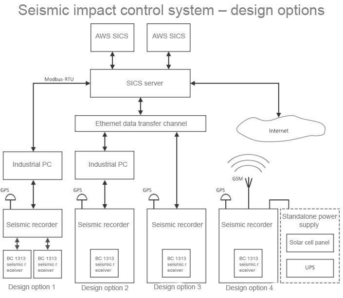
System design variants

Control systems usually have a tree-like structure. Seismic control system operating principle is as follows:

Each observation point is equipped with a seismic recorder (velocimeter or accelerometer). Acceleration signals by three space coordinates as well as power supply signal are transmitted from the seismic receiver to the seismic recorder input channels. Seismic receivers can be external (version 1) as well as integrated into the seismic recorder (versions 2, 3, 4).

Seismic recorder performs integrated digital clocks synchronization in real-time mode using GPS or PTP as well as digital processing of analog signals and transfer of digitized values at the average level of signals processing via Ethernet, USB or WiFi. This level can be implemented as an industrial PC located at the controlled object (versions 1 and 2). Besides the seismic recorders can be connected directly to the server (versions 3 and 4).

The data – events, states and/or constant data flow (16 kbps from each seismic receiver) is transmitted from the industrial PC or seismic recorder to the server through various communications channels. Seismic recorders offline versions can be equipped with solar panels and transfer the data via GSM/GPRS or WiMAX.

Depending on the connection scheme there are several variants of seismic control system topology:

Variants of construction of SKSV

Seismic recorders data synchronous transfer

When observation points are established, there are normally at least two seismic receivers with sensitive velocimeter and a broadband acceleration meter. In the case, if a high operational security level is required, up to 6 acceleration meters can be installed.

For the purpose of increasing the system reliability, one can install the industrial PC for preliminary data acquisition and processing. The processed data are more compact in volume if compared to the source data, hence, the data can be transferred via low-speed communication lines (IEC 60870-5-104, MODBUS RTU, dial-up modems, GSM/GPRS or as GSM/SMS notifications).

There are several schemes of seismic recorders synchronization:

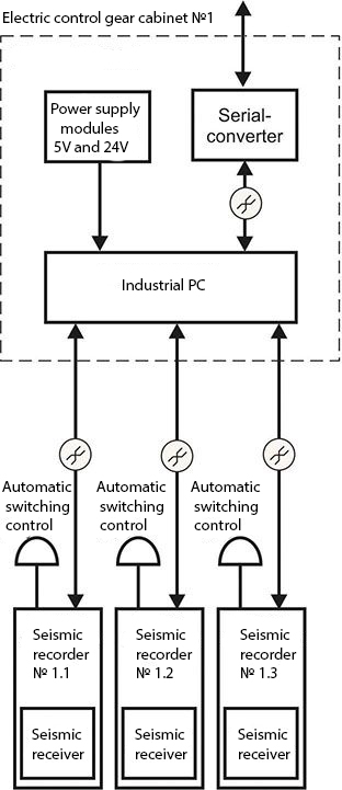
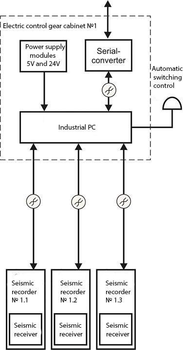
 individual— the seismic recorder is synchronized by integrated module and GPS antenna;

 group — industrial PC or one of the seismic stations is synchronized by GPS, while the remaining stations are synchronized by PTP via internet.

In order to implement synchronization via  PTP, there should be established a local network using copper or optical wire.

Custom synchronization

Custom-synchronization

Group synchronization

Group-synchronization

Installation of seismic receivers and seismic recorders

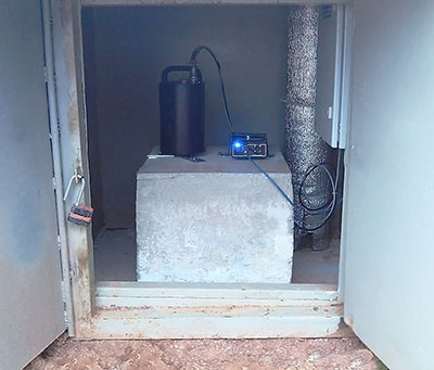
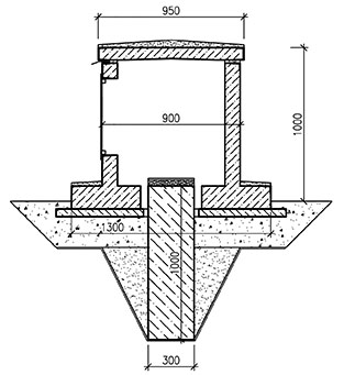
ZET 048 seismic receivers and seismic recorders are installed in special containments and on a concrete foundation.

Example of installing the ZET 048 seismograph

Example of installing a seismograph

Example of a technological solution for installing a seismograph on the street

Example of installing a seismograph

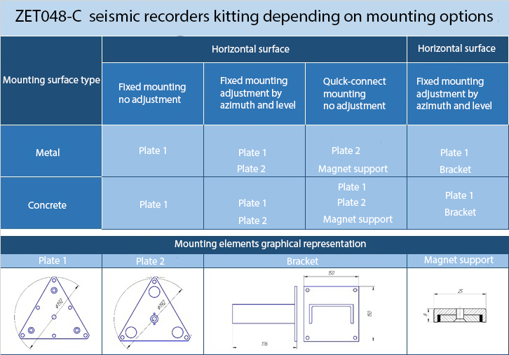
ZET 048-C seismic recorders are installed on a solid surface and are fixed with mounting panels. The panels are to be selected in accordance with the data specified in the table below:

Recording-of-seismographs

For installation in horizontal position one should use the element “Plate 1”.

«Wafer 2» is to be used when it is necessary to have adjustment possibility for horizontal mounting – i.e. azimuth rotation (360°) and angle adjustment (within the limit of ±3°).

For horizontal mounting one should use “Plate 1” together with “Mounting bracket” (U-piece min 12 mm with a welded plate with minimum 6 mm thickness). It is allowed to use U-piece for vertical surface mounting (U-piece min 12 mm) without a plate – in this case, the U-piece has to be welded directly to the controlled object.

In the case of mounting on a sloping surface the U-piece edge to be welded to the surface should be cut at an angle allowing horizontal (within the limit of ±3°) positioning of the U-piece.

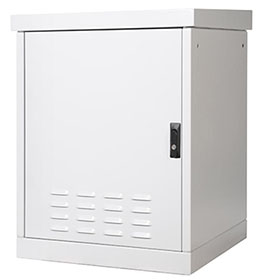
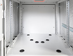
For the purpose of seismic recorder installation on the controlled objects, special cabinets can be used – the cabinet bottom should be detachable for the purpose of the sensor installation.

Cabinet for installing the seismograph
Cabinet for installing the seismograph ZETLAB

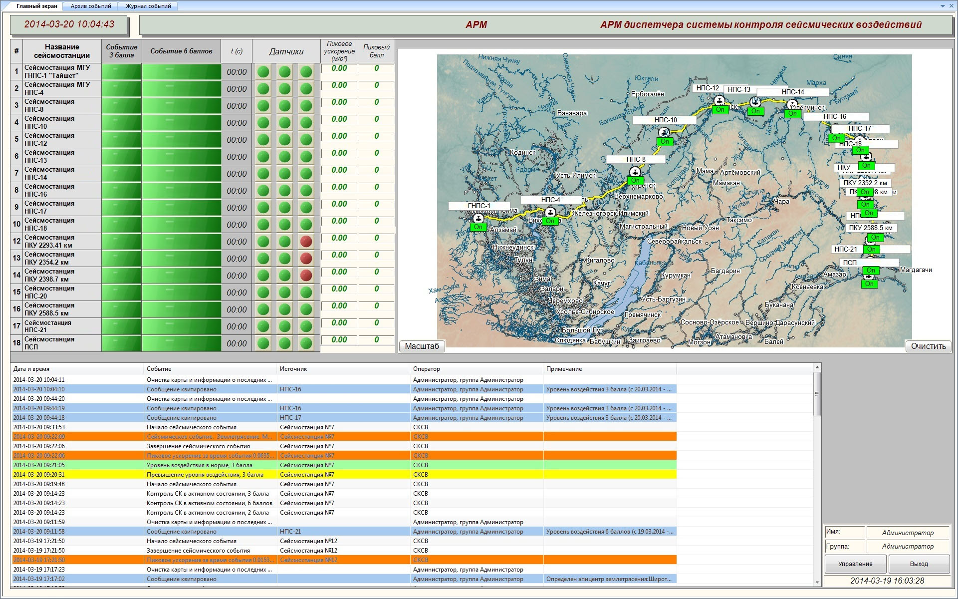
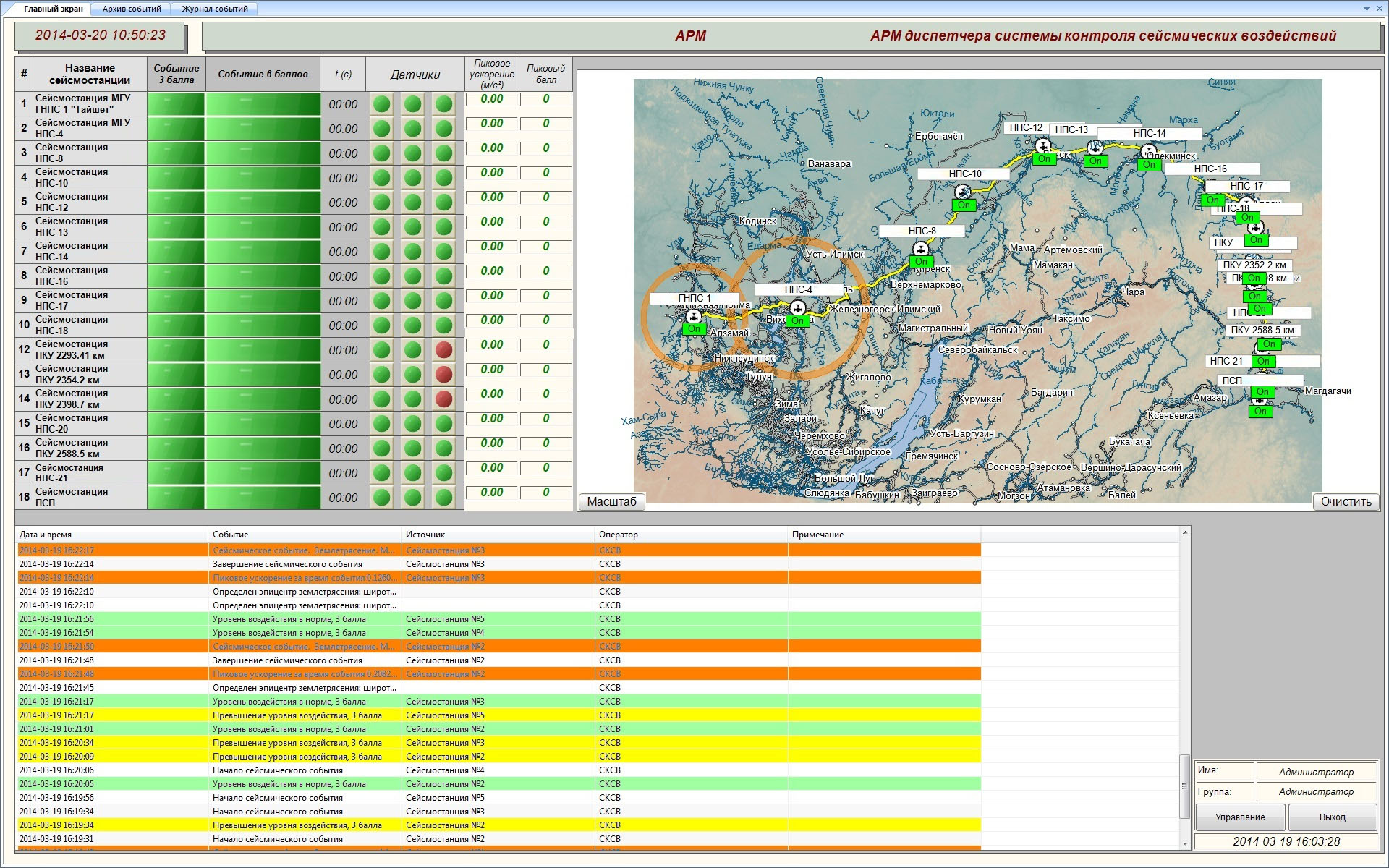
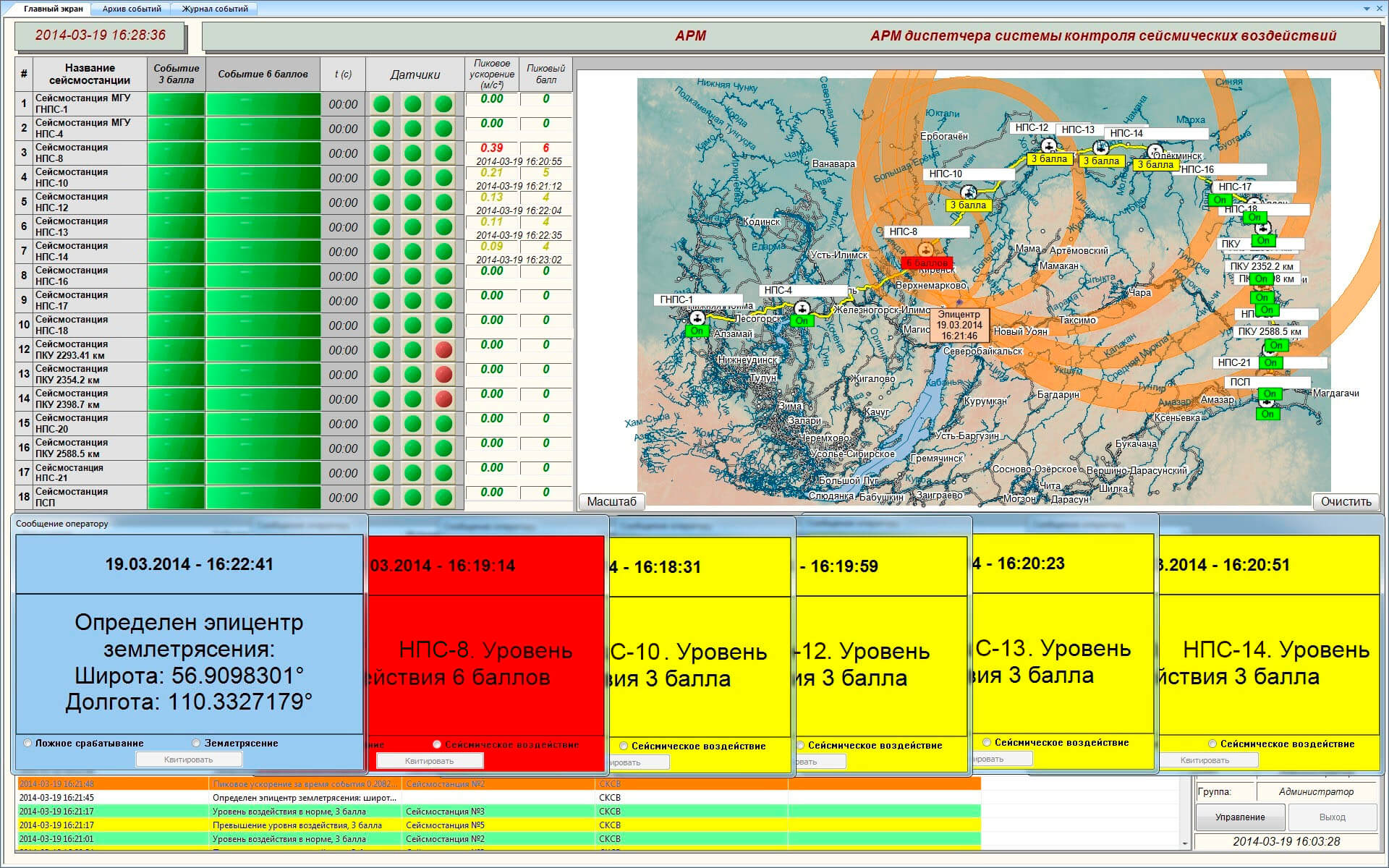
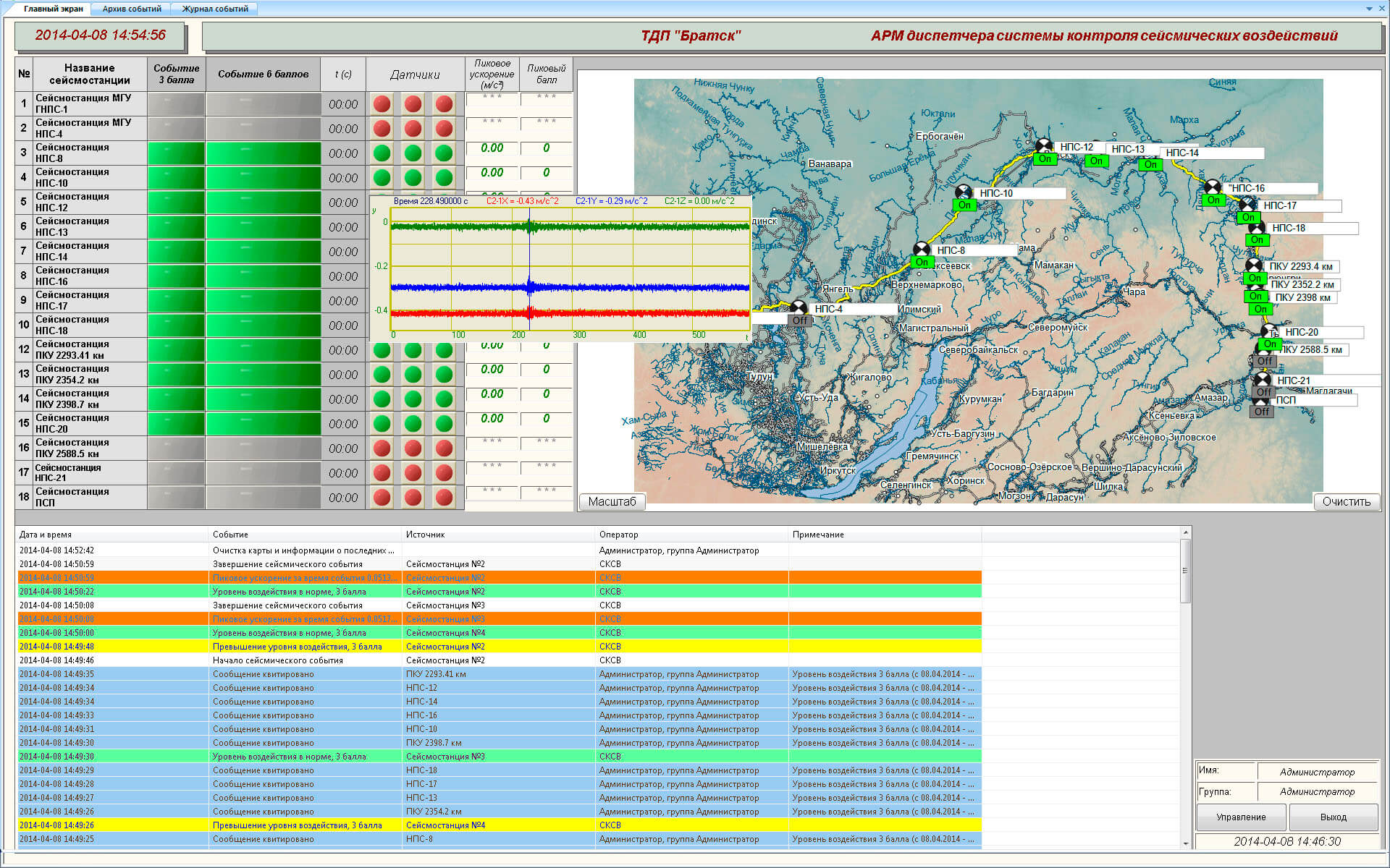
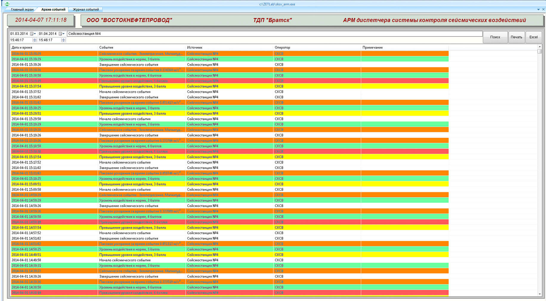
SCADA-project«Seismic Impact Control System»

System functions

  • Vibration acceleration physical values measurement

    and their conversion into electrical signals by seismic receivers integrated into seismic stations’ scope

  • Record and storage

    of all measured and digitized data to seismic station memory with a precise timing (minimum storage time – 90 days)

  • Historical data representation

    data representation upon request from the computing system – the data is retrieved from archive stored in seismic station or server memory

  • Self-diagnostics

    self-diagnostics and performance control of the seismic station elements

  • "Seismic event detection"

    non-seismical events and local man-made events filtering and processing based on multi-parameter statistical and time-spectral signal analysis

  • "Dangerous earthquake" signal

    upon exceeding the set seismic impact threshold within a specified period

  • "Training" software

    seismic events recording and model signals analysis in real-time mode, parameters quality evaluation for the analyzed signals of various types, relative comparison performance

  • Historical data view

    of messages and acceleration source signals within a specified period for each of the seismic receivers. View of long-term trends (day, month, year) for the purpose of dynamics and process development evaluation for all or several signals.

  • Amplification, coordination, analog-to-digital conversion

    of vibration acceleration signals from seismic receivers by the seismic recorder

  • Geo-referencing

    display of measured and calculated seismic event parameters with geo-referencing option

  • Continuous data transfer

    continuous seismic data transfer via TCP/IP closed protocol by communication channels

  • In-place verification

    remote in-place verification of seismic receivers and digital seismic recorders

  • "Seismic impact parameters evaluation module"

    calculation of earthquake focus location and seismic impact magnitude on the Richter scale (with the consideration of corrections on the earthquake focus location and seismic impact amplitude received from independent sources)

  • "Threshold detection"

    threshold detection and seismic impact level evaluation in accordance with MSK-64 requirements

  • Parameters adjustment

    possibility of Seismic control system multi-functional earthquake detector parameters adjustment after corresponding parameters selection in “Training” software in order to avoid false alarm signals and “Dangerous earthquake” signals

  • Medium-term forecast

    medium-term earthquake forecast using ZET 048-C seismic recorders with primary transducers of MTSS-2003 or CME-4211 type

System advantages

Full system automation

data processing, seismic situation representation

System scalability

depending on the particular task the amount of the seismic recorder channels can be increased up to 96

Warning messages

alarm signals in the case of the set critical values exceeding

In-place calibration

and sensors power supply control by an integrated generator and software features

To place an order for the System, please, fill the check-list below and send by the E-mail zetlab@zetlab.com

QUESTIONNAIRE