PID controller ZET 7190-R


- 2 control modes: PID controller/«Repeater»
- Used for stepper motor control
- CAN 2.0 data transfer interface
- Output voltage 0…5 V
ZET 7190-R — PID controller on CAN bus. It is used in automated systems for control signal forming.
POR (price on request)
* Minimum order value: from 7 700 USD
Specifications
of PID controller ZET 7190-R
| Technical specifications | |
|---|---|
| Number of channels | 2 |
| Control algorithm | PID controller (proportional-integral-derivative control) |
| Output voltage | 0…5 V |
| Maximum channel input current | 10 mA |
| Data transfer interface | CAN 2.0 |
| Operational specifications | |
| Dimensions | 65×34×14 mm |
| Weight | 35 g |
| Device power | from 9 up to 24 V |
| Consumed power | 1,5 W |
| Operational temperature range | from -40 up to +100 °C |
Measuring network connection and control scheme diagram
of PID controller ZET 7190-R
Settings adjustment of ZET 7190-R PID controller can be performed by connecting it to PC using interface converter via “Device manager”.
Connections designation for required signal generation
| Marking | Labelling | Function |
|---|---|---|
| 1 | OUT1 | Generator channel 1 |
| 2 | OUT2 | Generator channel 2 |
| 3 | +2,5 V | Base level |
| 4 | GND | General |
Connectors pins designation for connection to CAN line
| Contact | Function | Marking |
| 1 | +(9…24) V | Orange |
| 2 | CAN 2.0 line «H» | Blue |
| 3 | CAN 2.0 line «L» | White-blue |
| 4 | GND | White-orange |

Cophasal output channel connection in relation to the “gnd”

Differential output channels connection
in relation to base signal 2,5 V
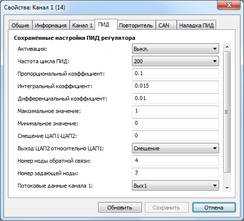
Configuration of ZET 7190-R PID controller
"PID" tab
| Parameter | Adjustable? | Acceptable values | Description |
|---|---|---|---|
| Activation | Yes | PID on/off | If PID mode is activated, repeater mode will be switched-off automatically |
| PID cycle frequency | Yes | 10 50 100 200 500 |
DAC frequency of data transfer to module output |
| Proportional gain | Yes | – | PID controller ratios |
| Integral ratio | Yes | – | |
| Differential ratio | Yes | – | |
| Max. value | Yes | – | Setting of DAC output value limitation |
| Min. value | Yes | – | |
| Displacement DAC1-DAC2 | Yes | – | Setting displacement value of DAC2 in relation to DAC1 |
| DAC2 output in relation to DAC1 | Yes | Displacement Inversion |
If “Displacement” mode is selected, displacement value will be taken from “Displacement DAC1-DAC2” parameter. If inversion mode is selected, DAC2 will have inverted from 2,5 V signal of DAC1. |
| Fedback node number | Yes | 2-63 | CAN network module address for feedback communication |
| Control node number | Yes | 2-63 | CAN network module address for reference signal |
| Channel 1 data flow | Yes | Output 1 P I D |
Selection of module signal data displayed by ZETLAB Software. Output1 – output voltage, P,I,D – PID controller ratios |
| Channel 2 data flow | Yes | Output 2 P I D |
The same as for the parameter «Channel 1 data flow» |
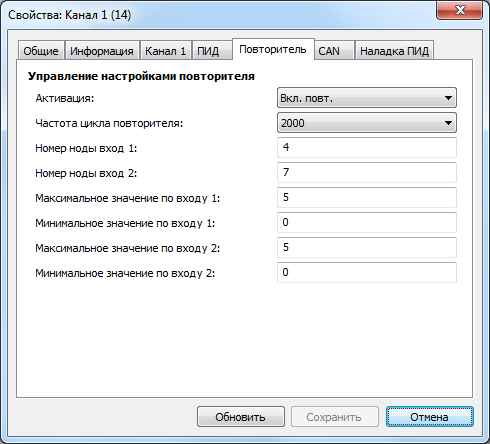
"Repeater" tab
| Parameter | Adjustable? | Acceptable values | Description |
|---|---|---|---|
| Activation | Yes | PID on/off | Repeater mode on/off. If repeater mode is activated, PID mode is disabled automatically |
| Repeater cycle frequency | Yes | 50 100 500 1000 2000 |
DAC frequency of data transfer to module output (irrelevant of input data) |
| Input 1 node number | Yes | 2-63 | CAN network node number (to be used as signal source) |
| Input 2 node number | Yes | 2-63 | The same as for the parameter «Input 1 node number» |
| Input 1 max value | Yes | – | Maximum value accepted by signal source. This value will be transferred to 5V physical signal at the output |
| Input 2 max value | Yes | – | Minimum value accepted by signal source. This value will be transferred to 0V physical signal at the output |
| Input 2 max value | Yes | – | The same same as for the parameter «Input 1 max value» |
| Input 2 min value | Yes | – | The same same as for the parameter «Input 1 min value» |
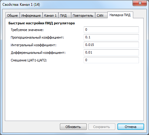
"PID adjustment" tab
| Parameter | Adjustable? | Description |
|---|---|---|
| Required value | Yes | Signal reference value |
| Proportional ratio | Yes | PID controller ratios |
| Integral ratio | Yes | |
| Differential ratio | Yes | |
| DAC1-DAC2 displacement | Yes | Setting displacement value of DAC2 in relation to DAC1 |
PID controller mode: configuration example
There are two tabs for configuration of the module in PID controller mode: “PID” and “PID adjustment”. “PID adjustment” tab serves for selecting adjustment ratios. The parameters set in this tab are applied upon “Save” key activation, however, these parameters are not saved in the non-volatile memory.
For changing the module settings, enable PID controller mode in “PID” tab, set PID frequency, max and min value, DAC2 output operation mode, feedback communication node number, reference node number, displayed data flow types for Output 1 and 2. Then enter the tab “PID adjustment”, select corresponding ratios depending on your task. After that copy the selected ratios from “PID adjustment” tab to “PID” tab.
Signal repeater mode: configuration
As the “Repeater” mode is activated, the module forwards a signal (obtained by means of linear conversion of the digitized signal from the digital module, node of which corresponds to that selected in ZET7190-R module) to analog outputs. Source digital signal in the range «max input X value» – «min input X value» is transformed into output signal in the range (0-5) V.
In the repeater mode ZET7190-R can be used off-line without connection to PC. In the case if the CAN network has a device with a set node number, ZET7190-R will use it and will form an output signal based on the data received.
In the “Repeater” mode the module can be used as a transmitter for “4-20 mA” interface. Input voltage range (0-5) V forms limitation for current loop operation mode 4-20 mA – current loop impedance max value is limited by 240 Ohm.
For changing module settings in the current output module one should:
1) calculate output voltage range
Ur_min = R*0,004,
Ur_max = R*0,02,
where R – is the current loop impedance.
2) calculate ratios depending on the input values range
k = ∆Ur/∆Uin,
where ∆Ur = Ur_max-Ur_min, ∆Uin – repeated values range
b = Ur_min-k* Uin_min
3) calculate ratios to be recorded in the sensor settings
min input value = -b/k
max imput value = (5-b)/k
Example. Settings of ZET7190-R module in signal repeater mode from ZET7112 for connection via current loop interface 4…20 mA to ZET7180-I.
R = 120 Ohm
Ur_min = 120*0,004 = 0,48
Ur_max = 120*0,02 = 2,4
∆Ur = 1,96, ∆Ur-in = 16 (mPa)
k = 0,12; b = 0,48
Min input value = -4
Max input value = 37,6667