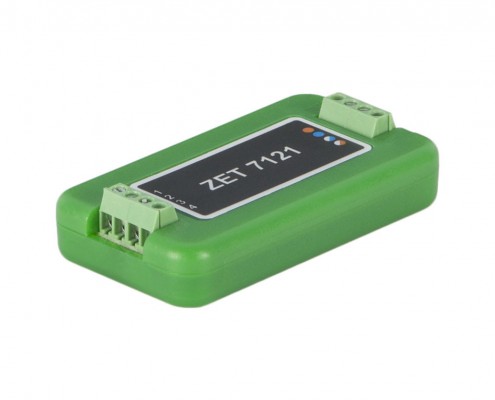
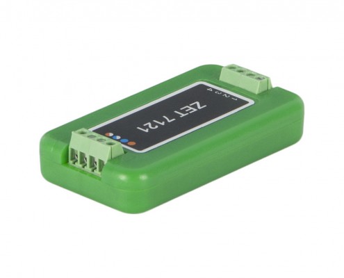
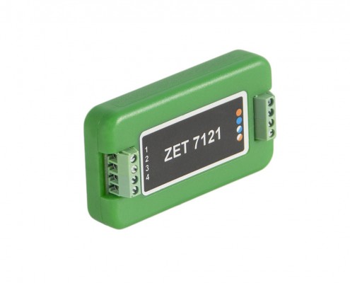
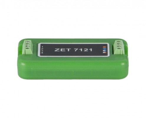
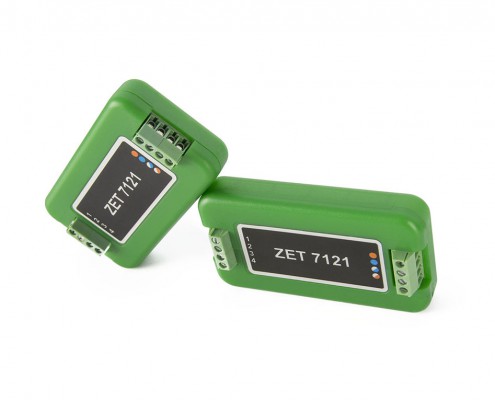
ZET 7121 Digital Temperature Sensor

  • digital output CAN 2.0
  • primary transducer type: resistance thermometers
  • CAN 2.0 interface

POR (price on request)

Specifications

of ZET 7121 Digital Temperature Gauges

Metrological Data
Measured value temperature
Nominal static characteristics (NSC) of connected PT 100P(0,00391), 50P(0,00391), Pt100(0,00385), Pt50(0,00385), 100C(0,00428), 50C(0,00428), Cu100(0,00426), Cu50(0,00426), 100N(0,00617), 50N(0,00617)
PT resistance signals measuring range 0.2 ~ 450 Ohm
Permissible basic percentage error limits ±0.05 %
Error in measuring in combination with PT (AA tolerance class) ±0.1 °C
Technical Specifications
Type of connected primary transducer (PT) Thermistor
PT feed current 1 ±0.05 mA
Data refresh rate 1, 10, 50 Hz
Data interface CAN 2.0
Transmission rate 100, 300, 1,000 kbps
Protection at interface inputs:
Overvoltage (1 A current)
Surge (350 W, 8/20 µsec)
19 V
28 V
Performance Specifications
Dimensions 65×34×14 mm
Weight 35 g
Power supply 9 to 24 V
Consumed power 0.6 W
Operational temperature range* -40 to +100 °C

*Operational measurement range of the gauge is determined by the specifications of the connected thermistor.

  • Hardware Versions

    Standard: laboratory design in a plastic cover (green)
    OEM: board covered with a sealing compound.
    Heavy Duty*: depending on the task specifics, this may be a version in a heavy duty cover (black) or location of the standard-design unit in an air-tight cover (with a transparent lid).
    *Cost is calculated individually

Advantages

of ZET 7121 Digital Temperature Gauges

Power Supply

primary transducers are fed from the measurement unit

No adjustment is needed

characteristics are stored in the measuring unit memory

Measurement Results

measurement results are transmitted in a digital form

Reliability

stable characteristics and high reliability during operation

Operation Principle

of ZET 7121 Digital Temperature Gauges

Digital temperature sensor ZET 7121 is intended for measuring temperature of liquid, solid, gaseous, and bulk mediums, unaggressive to the thermistor body material. Application scope: heat engineering, chemical industry, and metallurgy.

The digital temperature sensor consists of a thermistor and ZET 7121 measuring unit which converts the signal from the sensor to temperature values. Thermistor type is selected in accordance with the specifics of the task to be solved: measurement and accuracy required ranges, operation conditions.

Connection Diagrams

of ZET 7121 Digital Temperature Sensors

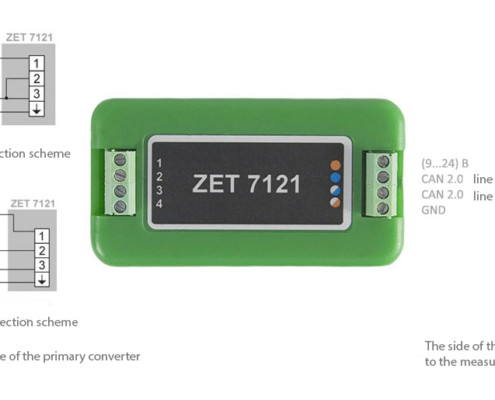
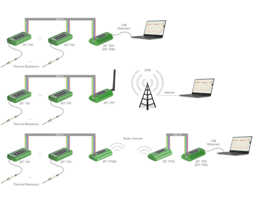
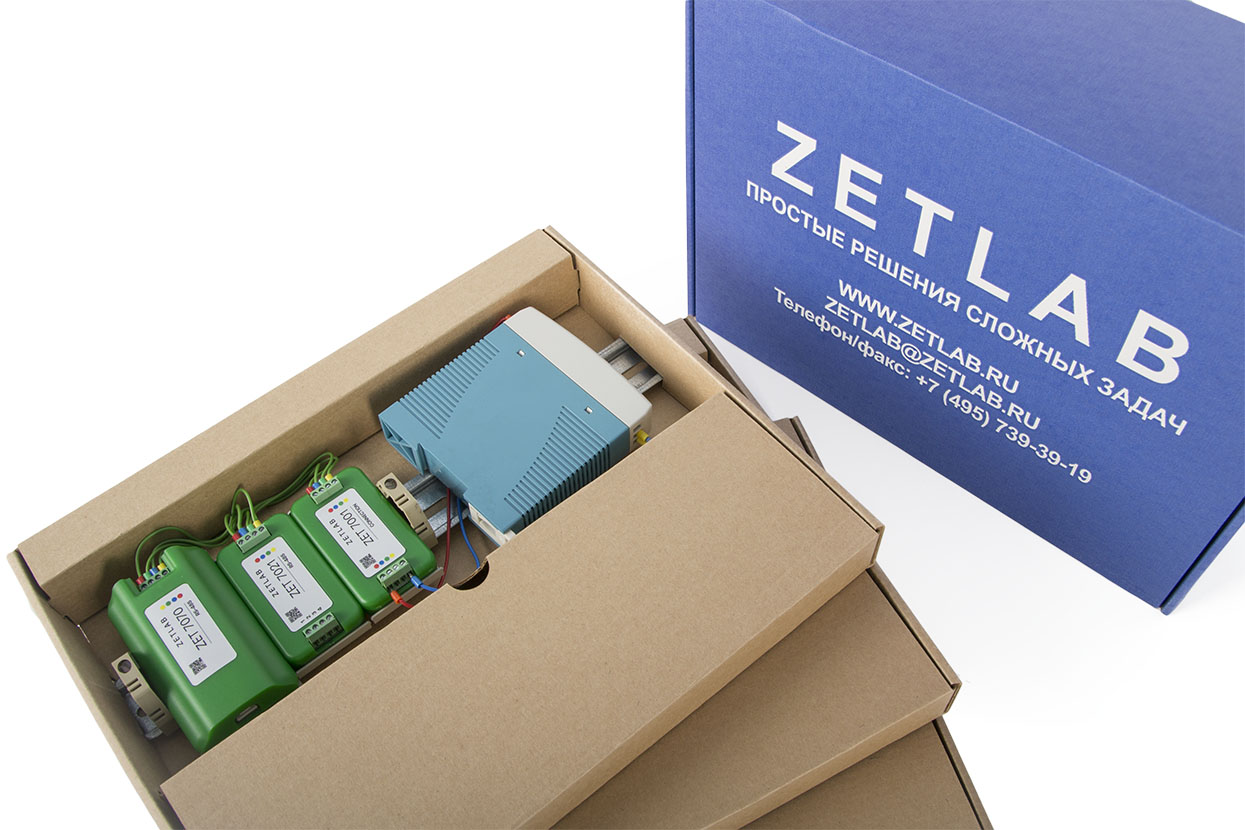
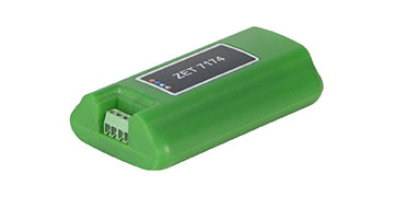
The digital gauges can be used for building distributed measurement networks. The ZET 7174 interface converter is used for connecting the measurement network to ZETLAB and ZETVIEW systems. The number of gauges connected to ZET 7174 shall not exceed 4. The ZETLAB software supports connection of up to 200 gauges to a single computer.

Control

of ZET 7121 Digital Temperature Sensors

Digital temperature sensor ZET 7121 starts measurement right after being powered on and does not require specific technical maintenance. All necessary settings are set during the primary and planned calibrations and stored in the measuring unit memory. The resulting temperature values are transmitted via CAN interface.

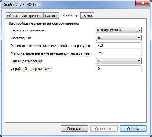
When a primary transducer is replaced, it is necessary to update the unit settings. For this purpose, connect the unit to a PC, launch “ZETLAB – Device Manager” software and set the sensor parameters on the “Thermometer” tab.

Configuration

Parameter Changeability Acceptable values Description
Thermistor Yes Resistor
100P; 50P;
Pt100; Pt50;
100C; 50C;
Cu100; Cu50; 100H; 50N
“Resistor” value is set when resistance is measured. Other parameters are set depending on the PT type used.
Frequency (Hz) Yes 10; 50 Frequency at which the gauge will generate data.
Minimum measured temperature value Yes This parameter defines the minimum value of the digital sensor measurement. The value is set in accordance with the technical specifications of the primary transducers used in combination with the digital sensor.
Maximum measured temperature value Yes This parameter defines the maximum value of the digital sensor measurement. The value is set in accordance with the technical specifications of the primary transducers used in combination with the digital sensor.
Measurement unit Yes °C
Om
Depends on the thermistor type selected (Ohm for “Resistor”, and °C for all other parameters).
Gauge serial number Yes The parameter is set only in case of a requirement for identifying the serial number of the primary transducer connected to the ZET 7X21 digital sensor.

Configuration 7121

Self-Diagnostic

The digital sensor self-diagnostics mechanism is a hardware and software implementation allowing to generate various test signals to the measuring “track” of sensors with no use of external equipment.

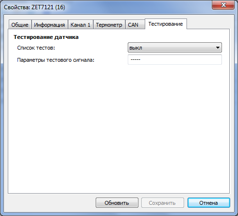
To start self-testing in digital sensors, use a separate tab, “Testing”.

Self-Diagnostic

A certain test corresponds to each test signal and has a unique identifier. The set of supported tests is stored in the digital sensor. The table below lists the tests available in ZET 7121.

Parameter Changeability Acceptable values Description
List of tests Yes Off Not tested
Test1 Resistance measuring
PPS external Synchronization signal generated by an external device. It is intended for controlling synchronization of several ZET 7121 sensors. Synchronization can be controlled in “Multi-Channel Oscilloscope”.
PPS internal Synchronization signal generated by the ZET 7121 digital sensor. It is intended for controlling synchronization of several ZET 7121 sensors. Synchronization can be controlled in “Multi-Channel Oscilloscope”.

After test selection, press the “Save” button; the signal received during self-testing comes via the measurement channel. The testing signal parameters are described in a text form in order not to bind particular types of sensors to certain tests. The “Test signal parameters” field describes the signal to be transmitted via the sensor measuring channel. The table below lists possible types of signal.

Signal Designation Type of Signal Parameters 
DC Constant signal (values are displayed on the DC voltage meter). LE: “Required resistance”: “Resistance tolerance”
TM “Signal analysis time”, the time for signal control (set the minimum signal analysis time for the tests which imply transition processes or which simply are long)
Example:
DC; LE:227:2; TM:3
Constant signal: 227±2 Ohm, the signal is controlled during at least 3 seconds.

Test impact types

AC - alternating signal

FR: «Required frequency value»: «Frequency tolerance» – alternating signal frequency;

AM: «Required signal amplitude value»: «Signal amplitude tolerance» – alternating signal amplitude;

OF: «Generated signal bias»: «Generated signal bias tolerance» – generated signal bias;

TM: «Signal analysis time» – signal control time (minimal signal analysis time for transient processes or long-time tests)

Example:
AC;FR:0.5:0.01;AM:0.4:0.002;OF:0.1:0.0001;TM:5
Alternating signal with frequency: 0.5 ± 0.01 Hz, amplitude: 0.4 ± 0.002 V, bias: 0.1 ± 0.0001 V, minimal signal control time – 5 s.

DC - constant signal

LE: «Required signal level»: «Signal level tolerance» – generated signal level.

TM: «Signal analysis time» – control signal time (signal analysis minimal time for transient and long-time processes tests)

Example:
DC;LE:0.5:0.001;TM:5
constant signal: 0.5 ± 0.001 V, minimal signal control time – 5 s.

ST1 - stepwise change

AM: «Minimal value»: «Maximum value» – change range.

TM: «Signal setting time» – time before signal control start

Example:
ST1;AM:100:200;TM:5
stepwise change: for 100..200 units, minimal signal control time – 5 s.

ST2 - stepwise change

MD: «Minimal change»: «Maximum change» – change amplitude.

TM: «Signal setting time» – time before signal control start

Example:
ST2;MD:10:10.5;TM:6 
stepwise change: for 10..10.5 units in modulus, minimal signal control time – 6 s.

PPS - Pulse-per-second signal

SP: «Acceptable counts deviation» – amount of counts before or after start of a second.

Level change to be checked one time in a second.

Example:
PPS;SP:2 –
the change should take place in the beginning of a second, 2 counts.

Device type is selected from the dropdown list. In order to select a device, pick an element with left mouse key and choose a device to be checked from the list.

Use selector to set particular test. To set the test number click the number with left mouse key and set the required value by scroll. If the self-check is on, the selector will not be available until the user stops the project or the self-check is over. There is a key for start / stop of the process. The green key means that the diagnostics process is on, grey key stands for  for idle state.

Indicator is a timer showing the elapsing time of the current test. The countdown is started after beginning of any test. Test results are available in the log.

Basic configuration

of digital temperature meters ZET 7121

Standard equipment

Digital temperature sensor ZET 7121 basic configuration includes:

  • Digital temperature sensor ZET 7121;
  • DIN – rail mounting panel for plastic modules 71×39;
  • set of operational documentation.

POR (price on request)

Order form - If you want to place an order or to make a request regarding technical specifications of particular product, fill out the form below:

Data protection notification

Please note that the personal data provided by you is used exclusively for the purposes of fulfilling our contractual obligations, including, but not limited to: issuing invoices, delivery documents, documentation relating to customs clearance process, etc. We do not provide your personal data to any third party except for the purposes relating to our direct contractual obligations. Upon completion of order processing and expiry of the warranty period for the Products provided by our Company, we do not store or process any of your personal data. Please note, that our Company’s Confidential policy does not imply any advertising or marketing activities with the use of your personal data (including your Company name, address, your E-mail, phone number and other information provided by you with a view to placing an Order and organization of the Delivery).

Necessary measuring equipment

supplied upon special order

ZET 7174
ZET 7174
USB connection

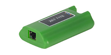
ZET 7176
ZET 7176
Ethernet connection