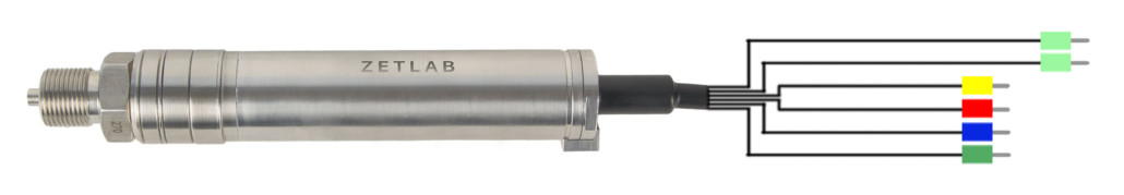
ZET 7112-I VER.2 digital gauge pressure


- Integrated primary transducer
- Ready for operation
- CAN 2.0 interface
POR (price on request)
* Minimum order value: from 7 700 USD
Specifications
of ZET 7112-I VER.2 digital gauge pressure
| Metrological Data | |
|---|---|
| Measured value | overpressure |
| Upper limit of pressure measuring range | 0,1 MPa; 0,16 MPa; 0,25 MPa; 0,4 MPa; 0,6 MPa; 1 MPa; 1,6 MPa; 2,5 MPa; 4 MPa; 6 MPa; 10 MPa; 16 MPa; 25 MPa; 40 MPa; 60 MPa; 80 MPa; 100 MPa; 160 MPa |
| Resolution | 0.005 % |
| Relative measurement error (from the measured value) | 0.1 % |
| Additional measurement error (due to temperature change) | 0.1 %/10 °C |
| Parameters diagnostics | power supply control data quality control sensing element integrity control |
| Technical Specifications | |
| Data refresh rate | 1, 5, 25, 100, 200 Hz |
| Data transmission interface | CAN 2.0 |
| Transmission rate | 100, 300, 1000 kbps |
| Operational Specifications | |
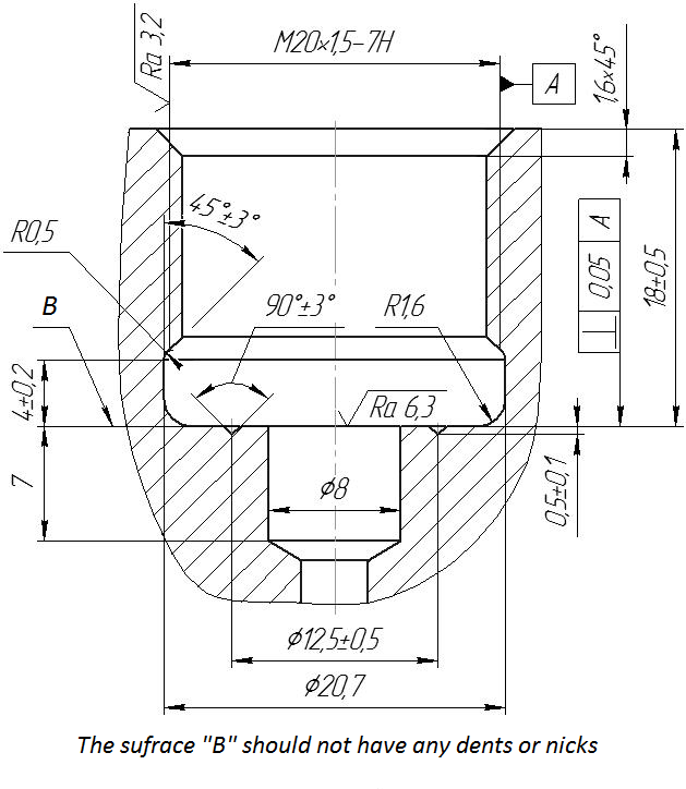
| Dimensions | ∅31.5×160 mm |
| Weight | 380 g |
| Power supply | 9 to 24 V |
| Consumed power | 0.5 W |
| Reverse polarity protection | yes |
| Operational temperature range | -40 to +100 °C |
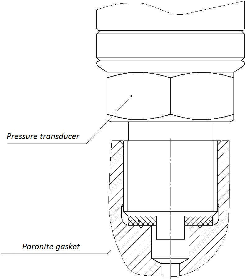
| Operation environment | liquids and gases non-aggressive to titanium alloys and stainless steels |
| Design | Standard (IP63 protection degree) Ex-proof* (1ExdIIAT6X type explosion protection, cable 4 m) |
| Overpressure | 1.5 × Upper limit of pressure measuring range |
| Electromagnetic Compatibility, EMC | |
| IEC 61000-4-2, ESD | contact 4 kV, air 8 kV |
| IEC 61000-4-4, EFT | power supply 0.5 kV; signal 0.25 kV |
| IEC 61000-4-5, Surge | 500 V |
* Cost is calculated individually