
Resistance, capacity and inductance meaurements
Measuring resistance, capacity and inductance by means of comparative method, i.e. relative to load resistor with a known resistance value.
Resistance measurements
Connection of measuring and load resistors to ADC DAC modules is performed in accordance with the scheme specified in the Figure 1. Each resistor is connected to two ADC inputs thus forming differential input, i.e. measuring channel. ADC input channels are activated in “Setting ADC DAC channels parameters”. It is necessary to enable the channels to which the resistances are connected and to set differential channel type for them (figure 2).

Figure 1 |
 Figure 2 Figure 2 |
Input channels should be set for voltage measurements in differential mode (the settings are available in “Editing measuring channels parameters” program). Figure 3 shows “Editing measuring channels parameters” program window with settings corresponding to the resistors connection scheme shown in Figure 1. Channels names are selected by the user. In this case there is resistor (resistance of which is to be measured) connected to the channel – this channel is “reference channel”. The channel with load resistor connected is called “reference channel”.
 Figure 3
In order to provide power supply for the resistances, integrated module generator can be used (DAC output). To use it, launch “Signal generator” program (figure 4), set the parameters of the signal to be produced and click “Add” and “Enable” keys. The signal will have arbitrary frequency, but it should not be divisible by 50 Hz and 60 Hz (industrial frequencies in Europe and USA correspondingly). The signal level should provide power supply for the resistances in such a way, so that the voltage level would not exceed 10 mA.
 Figure 4
“ZETFormula” program is used for output channels measurements results processing. Since the load and measuring resistors are connected sequentially, the current values for them are as follows:
Il=Imeas=I (1)
Hence:
Ul=I·Rl, Umeas=I·Rmeas (2)
And it follows that:
Rmeas=(Umeas/Ul)·Rl (3)
In “ZETFormula” program, set the name of the channel to which Rmeas is connected to in the field , and in the field – name of the channel to which Rl is connected to, set “100” value for load channel of the load resistor. “ZETFormula” program forms virtual channel (with “Ohm” as measuring unit) displaying measurements results. This channel is compatible with all programs from ZETLab scope (voltmeters, oscillographs, etc.).
 Figure 5
For measurements results representation one can use DC voltmeter set for virtual channel signal level measurement, formed by “ZETFormula” program (figure 6).
 Figure 6
Figure 7 shows result of “Multi-channel oscillograph” program operation. Three channels to be displayed have been selected: physical channels (with load and measurement resistances connected), and a virtual channel formed by “ZETFormula”. From the upper two oscillograms one can see that the measuring channel signal voltage is 2 times less than that of the reference channel. Hence, resistance of the measuring resistor is two times less than that of the loading resistor. Since Rl=100 Ohm, Rmeas=50 Ohm (in accordance with formula 3). The same result is displayed at the third oscillogram – “ZETFormula” program calculation result.
 Figure 7
Capacity and inductance measurements
Capacity and inductance connection is performed in the same way as connection of resistance. Connection schemes are shown in Figures 8 and 9 respectively. Settings of the programs “ADC DAC parameters settings”, “Editing parameters files”, “Signals generator” are similar to those for resistance measurements. The difference is in the formulas for capacity and inductance calculation and measuring units of “ZETFormula” virtual channel.
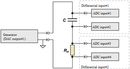
Figure 8 |
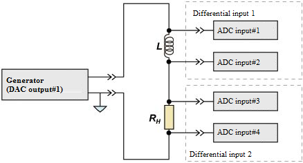
Figure 9 |
Reactive impedance is calculated based on capacity and inductance in the following way:
Rmeas=1/(ω·C)=1/(2Πf·C), Rmeas=ω·L=2Πf·L (4)
where f – generator signal frequency. From (4) it follows that:
C=Rmeas/(2Πf), L=Rmeas·2Πf (5)
If in (5) equation (3) is used instead of Rmeas, then:
C=[(Umeas/Uн)·Rн]/(2Πf), L=[(Umeas/Uн)·Rн]·2Πf (6)
Figure 10 shows program window for capacity and inductance calculation: 100 – resistance of load resistor, 160 – feeding signal frequency.
 Figure 10
Note: for measuring resistance/capacity/inductance by several channels it is possible to use a single load resistor for sequential connection scheme of resistance/capacity/inductance. In the case of parallel connection to each resistance/capacity/inductance there is connected a load resistor, in relation to which the measurements are performed.
See also:
SCADA-project”Resistance measurement”.