Stress-strain state control
of engineering structures
Stress-strain state is one of the structural strength criteria, which, however, can not be evaluated by means of direct techniques. As a rule, the stress-strain state is detected through deformation or some other processes that are related to the change of stress-strain state (like a change of optical or magnetic properties, frequency characteristics, etc).
Change of stress-strain characteristics of structures may be caused by a number of factors: low quality of building materials, wrong sequence of construction works, uneven foundation settlement, mistakes in load factor design, etc.
The subsystem for stress-strain state control is used for timely detection of stress-strain state changes of bearing structures and buildings that may lead to the transition of the building state from operational into the state of failure.
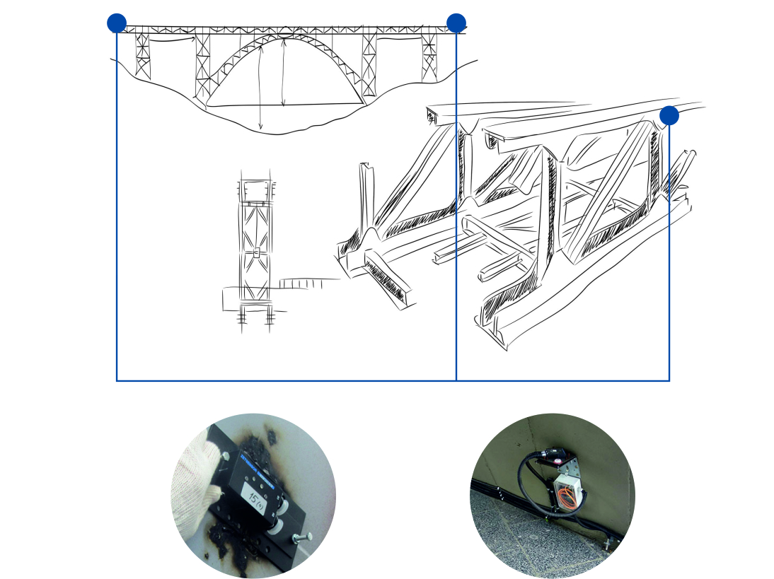
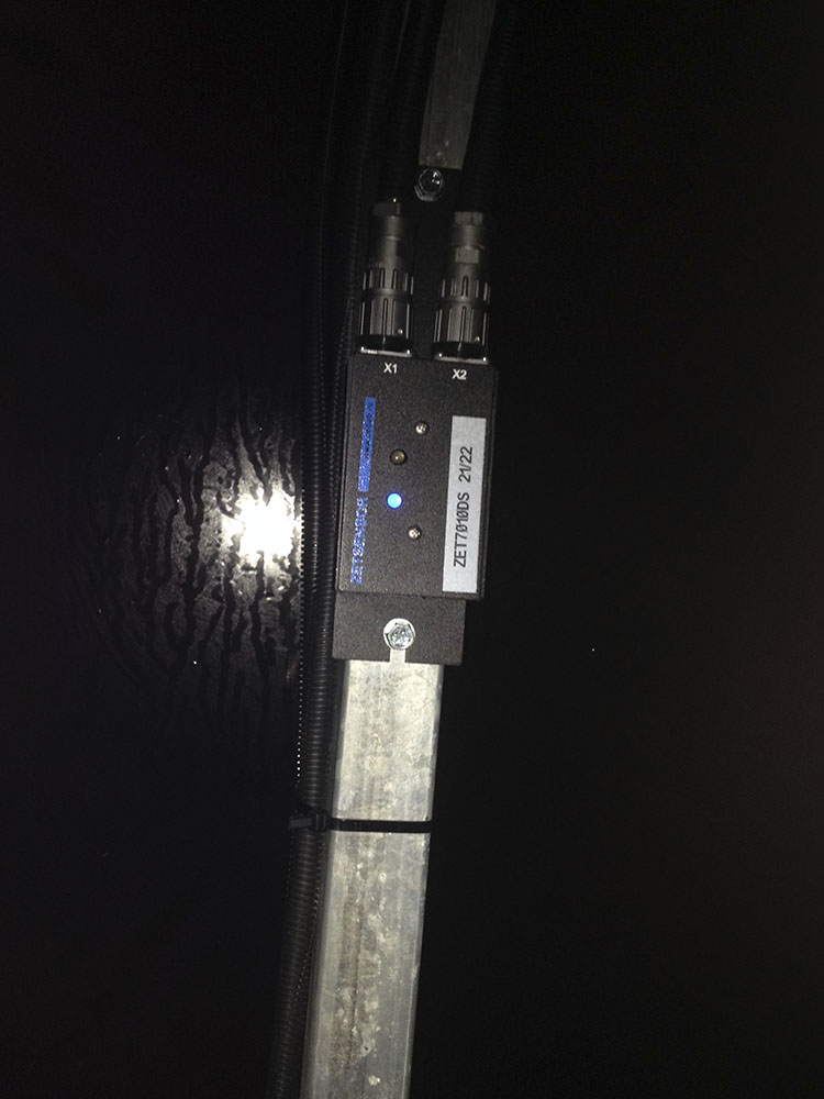
The subsystem for stress-strain state control is based on ZET 7X10-DS digital strain gauges and ZET 7X54 digital inclinometers which enable bearing structures deformation and bending control.
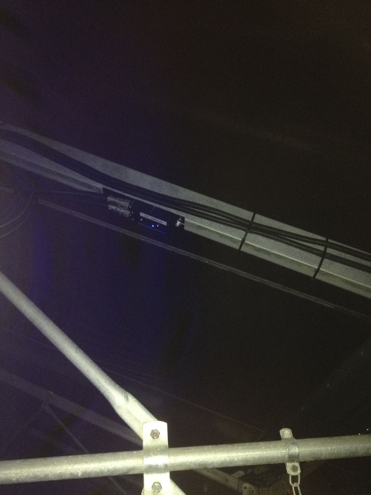
ZET 7X10-DS strain gauges are mounted on the elements, deformation of which is to be controlled (intermediate slabs, bearing walls, ceiling elements, beams, etc.).
General specifications
| Controlled parameter | Tensile-compression |
| Module/digital sensor type | ZET 7010-DS ZET 7110-DS |
| Measuring unit | µm/m |
| Measuring range | -300…+300 |
| -1800…+1800 | |
| Minimal registered value | 0,2 |
| 1,2 | |
| ALARM – bottom threshold level | 10 |
| 60 |
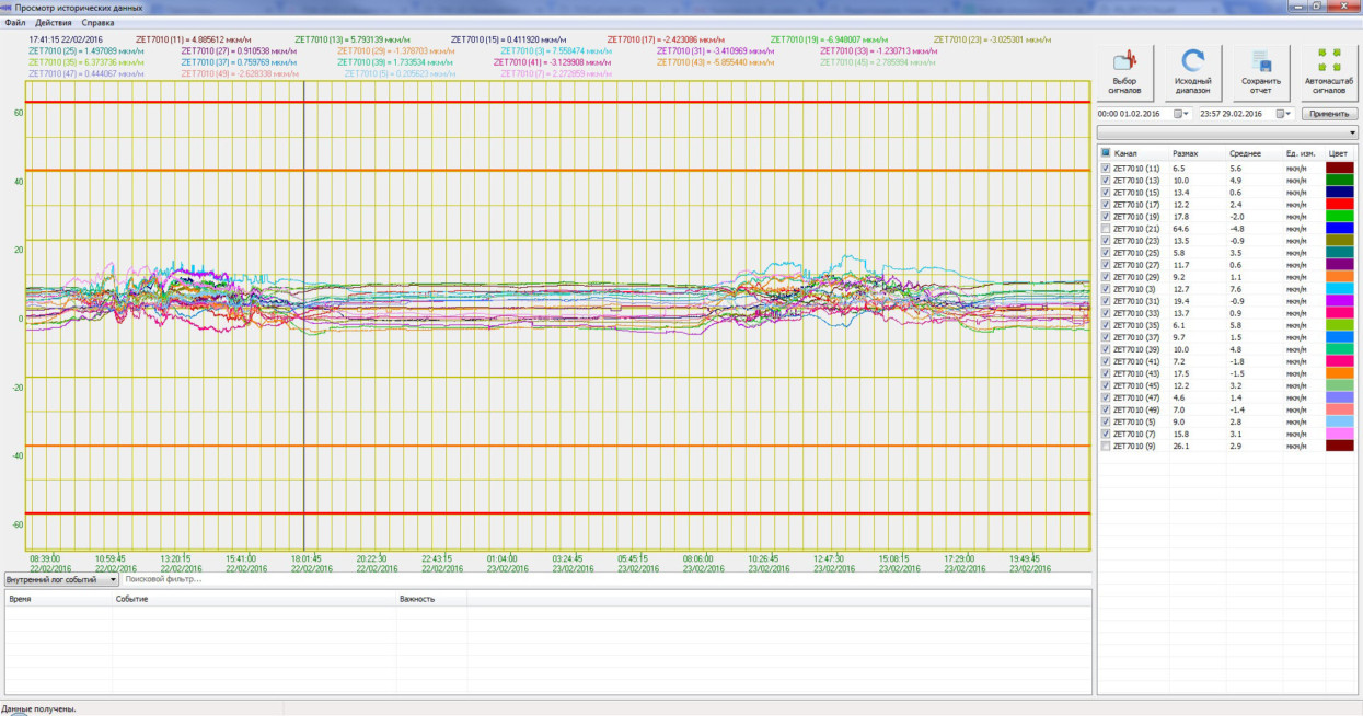
In the course of its operation “Stress-strain state control” subsystem compares the registered values with the preset warning and alarm threshold values. If the threshold values are exceeded, a “Warning” signal (the beige line in the diagram) or a “Danger” signal (the red line in the diagram) is formed.
Signals from the sensors are transferred to data acquisition node via Ethernet interface. Then the data is transferred to the server for further storage. Each of the registered signals is compared with threshold values. In the case if the threshold level is exceeded there is formed an alarm notification for the operator.
Threshold level values (for structure tilt and elements relative displacement) are calculated in accordance with the applicable normative and technical documentation for the particular structure type.
The figure below shows an example of “Stress-strain state control” subsystem operation. The signals trends shown in the diagram depict stress-strain state value of building’s ceiling structure for the period of 48 hours.
Depending on the time of the day, ZET 7X10-DS digital strain gauges values were changing. There is a clear difference between working time (8 a.m.-6 p.m.) and off-hours (6 p.m. -8 a.m.).
Presence of minor additional load is fixed by digital sensors and is shown in the diagram. It proves that the “Stress-strain state control” subsystem is sensitive to changes of the relative deformation load at the mounting point. It is also possible to track the dynamics of the corresponding values in real-time mode. Metrological self-check option enables in-place digital sensors diagnostics in the course of measurements performance without de-installation of the sensors.
It should be noted, that in order to obtain precise strain-gauges readings, it is necessary to mount them in the areas of stress-strain concentration (the areas should be under load of their own weight, snow and wind impact). These areas location can be determined by means of stress-strain buildings structure calculation.


