
GETTING STARTED
with the “Service operations with ZET 7xxx” software
The “Service operations with ZET 7xxx” program is launched from the main menu of ZETLAB software package by pressing the “Service operations with ZET 7xxx” button.
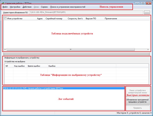
The window of the “Service operations with ZET 7xxx” program can be divided into several main areas:
- Control Panel;
- Table of connected devices;
- “Information for the selected device” table;
- Event log;
- Shortcuts;
Menu for selecting the device firmware update directory.
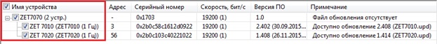
The connected devices table contains the following information:
- “Device name”: device type;
- “Address”: device address in the measuring circuit;
- “Serial No”: a unique number of the device;
- “Rate, bps”: “Exchange rate” and “Parity check” parameter values;
- “Software version”: firmware version number;
- “Note”: additional information.
To display the connected devices of specific interface converters in the table, enter “Settings” – “Operations with wizards” menu in the control panel of the “Service operations with ZET 7xxx” program, and select the required types of converters from the pop-up menu.
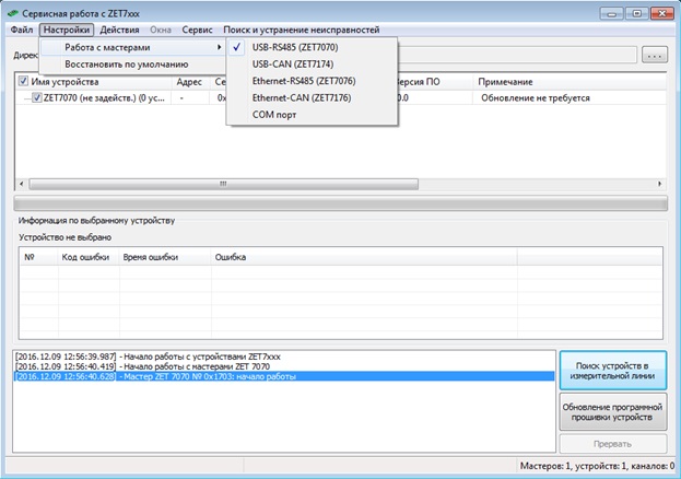
To display the digital sensors connected to the active interface converters, press the “Search for devices in the measuring line” button.
After the search for the digital sensors is complete, list of interface converters found by the program and connected to this computer will be displayed in the table of connected devices on the first root level of “Device name” cell and list of digital sensors connected to the relevant interface converters, on the second root level.
To ensure proper operation of the digital sensors, set “Exchange rate” and “Parity check” of the digital sensors in strict compliance with the values set for the interface converter. The “Exchange parameters autoconfiguration” option is intended for resolving conflicts between the digital sensors and interface converters in case of these parameters mismatch.
The “Exchange parameters autoconfiguration” option is enabled as follows:
- Set “19200” for the “Exchange rate” parameter, and “1” for the “Parity check” parameter for the required interface converter.
- Turn off the power supply of the digital sensors connected to this interface converter.
- Turn on the power supply to the digital sensors.
- Press the “Search for devices in the measuring line” button at least 5 seconds later.
- The digital sensors will enter a special operation mode for setting the “Exchange rate” and “Parity check” parameters for all digital sensors within the selected measuring circuit in accordance with those parameters of the interface converter.