Establishing Bridge Circuits
The resistive strain sensors are designed for measuring the stress on surface of different elements. They can be used to measure compression and stretch, twisting, bending, and calculate the force applied to an object.
Below you can find various connection pattern options for connecting the resistive strain sensors to ZETSENSOR measuring modules, as well as instruction on module configuration.
- Uniaxial Strain.1 resistive strain sensor, 1 resistance, R≈R1. Temperature compensation — no. Bending compensation — no.
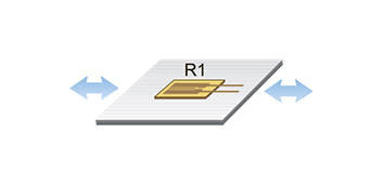
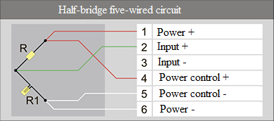
Configuration:
Settings/Circuit: Half-Bridge.
Settings/Method: Transfer factor.
Resistive Strain Sensor/Status: On.
Resistive Strain Sensor/Sensitivity: S=4/K.
2. Uniaxial Strain.2 resistive strain sensors, 1 resistance, R≈R1+R2. Temperature compensation — no. Bending compensation — yes.
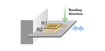
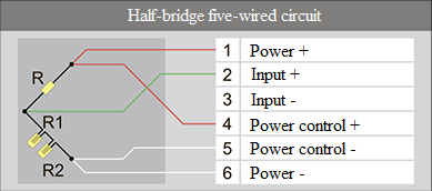
Configuration:
Settings/Circuit: Half-Bridge.
Settings/Method: Transfer factor.
Resistive Strain Sensor/ Status: On.
Resistive Strain Sensor/ Sensitivity: S=4/(2*K).
3. Uniaxial Strain.2 resistive strain sensors, R2≈R1. Temperature compensation — yes. Bending compensation — no.
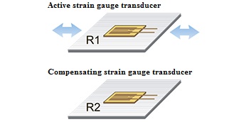
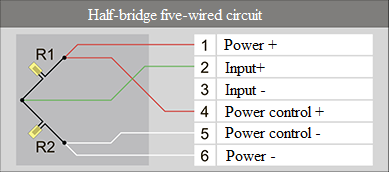
Configuration:
Settings/Circuit: Half-Bridge.
Settings/Method: Transfer factor.
Resistive Strain Sensor/ Status: On.
Resistive Strain Sensor/ Sensitivity: S=4/K.
4. Uniaxial Strain.2 resistive strain sensors, R2≈R1. Temperature compensation — yes. Bending compensation — no.
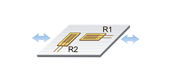
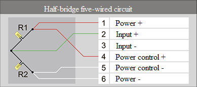
Configuration:
Settings/Circuit: Half-Bridge.
Settings/Method: Transfer factor.
Resistive Strain Sensor/ Status: On.
Resistive Strain Sensor/ Sensitivity: S=4/((1+ν)*K).
ν – Poison’s ratio
5. Uniaxial Strain. 4 resistive strain sensors, R4≈R3≈R2≈R1. Temperature compensation — yes. Bending compensation — no.
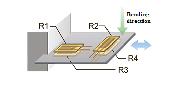
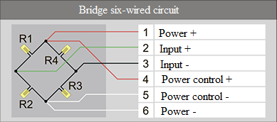
Configuration:
Settings/Circuit: Bridge.
Settings/Method: Transfer factor.
Resistive Strain Sensor/ Status: On.
Resistive Strain Sensor/ Sensitivity: S=4/((1+ν)*2*K).
6. Uniaxial Strain. 4 resistive strain sensors, R4≈R3≈R2≈R1. Temperature compensation — yes. Bending compensation — no.
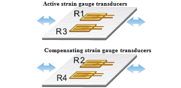
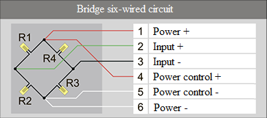
Configuration:
Settings/Circuit: Bridge.
Settings/Method: Transfer factor.
Resistive Strain Sensor/ Status: On.
Resistive Strain Sensor/ Sensitivity: S=4/(2*K).
7. Bending Strain. 1 resistive strain sensor, 1 resistance, R≈R1. Temperature compensation — yes.
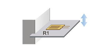
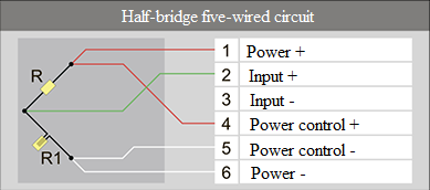
Configuration:
Settings/Circuit: Half-Bridge.
Settings/Method: Transfer factor.
Resistive Strain Sensor/ Status: On.
Resistive Strain Sensor/ Sensitivity: S=4/K.
8. Bending Strain. 2 resistive strain sensors, R2≈R1. Temperature compensation — yes.
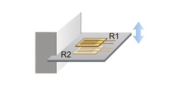
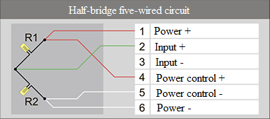
Configuration:
Settings/Circuit: Half-Bridge.
Settings/Method: Transfer factor.
Resistive Strain Sensor/ Status: On.
Resistive Strain Sensor/ Sensitivity: S=4/(2*K).
9. Bending Strain. 4 resistive strain sensors, R4≈R3≈R2≈R1. Temperature compensation — yes.
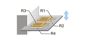
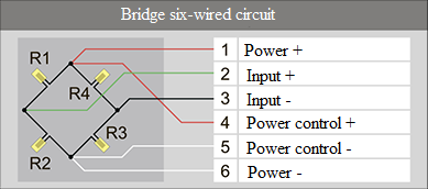
Configuration:
Settings/Circuit: Half-Bridge.
Settings/Method: Transfer factor.
Resistive Strain Sensor/ Status: On.
Resistive Strain Sensor/ Sensitivity: S=4/(4*K).
10. Twisting Strain. 2 resistive strain sensors, R2≈R1. Temperature compensation — yes.
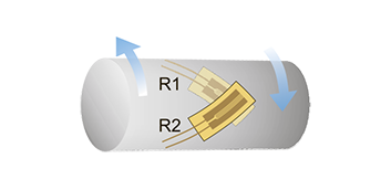
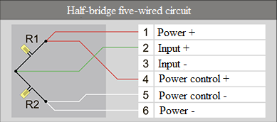
Configuration:
Settings/Circuit: Half-Bridge.
Settings/Method: Transfer factor.
Resistive Strain Sensor/ Status: On.
Resistive Strain Sensor/ Sensitivity: S=4/(2*K).
11. Twisting Strain. 4 resistive strain sensors, R4≈R3≈R2≈R1. Temperature compensation — yes.

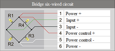
Configuration:
Settings/Circuit: Half-Bridge.
Settings/Method: Transfer factor.
Resistive Strain Sensor/ Status: On.
Resistive Strain Sensor/ Sensitivity: S=4/(4*K).
K – sensitivity of resistive strain sensor (datasheet value).
Relative Strain Measurement with ZETSENSOR
The strain of the analyzed object leads to a relative change in output voltage from strain gauge half-bridge (or full-bridge) circuits. The relative change of the output voltage is described by formula ΔU=e0/U (mV/V),
where e0 is the change in output voltage of strain gauge circuit
U is power voltages of strain gauge circuit
The calculated relative strain ε0 (mm/m) is correlated to recorded value of the relative change in the output voltage of strain gauge circuit according to the formula:
ε0 = ΔU*S
where S is the sensitivity of the applied strain gauge connection circuit (the formula for calculation is shown in Table 1 and depends on the selected connection circuit)
When recording the relative strain with ZETSENSOR modules, Relative Strain should be selected as measuring type in the Device Manager, and the adjusted (depending on the required strain measurement units) value of the sensitivity coefficient in accordance with Table 2 shall be set.
Table 2
| Strain Measurement Units | Adjustment of Sensitivity Set for ZETSENSOR |
| mm/m | S |
| µm/m | S*1000 |
| m/m | S/1000 |
| % | S/10 |
Material Stress Measurement with ZETSENSOR
The stress occurring in the material can be calculated within its elastic strain according to the strain of the analyzed object, which is associated with the recorded (using ZETSENSOR) relative change in the output voltage of the half-bridge or full-bridge circuit according to the formula: ε0 = ΔU*S,
where S is the sensitivity of the applied strain gauge connection circuit (the formula for calculation is shown in Table 1 and depends on the selected connection circuit)
Note: When measuring the stress, the sensitivity ratio should be adjusted according to the formula S/10
Material stress is related to its relative strain according to the formula:
σ=ε0*E= ΔU*S*E
where E is the modulus of elasticity of the material of the analyzed object (values for the modulus of elasticity of certain materials are provided in Table 3)
Table 3
| Material | Value of the Modulus of Elasticity E (MPa) |
| Aluminum | 69,000 |
| Copper | 100,000 |
| Steel | 210,000 |
| Glass | 60,000 |
| Concrete | 20,000 |
When recording the material stress change with ZETSENSOR modules, Stress should be selected as measuring type in the Device Manager, and the adjusted for % units (see Table 2) value of the sensitivity coefficient, along with the material-specific modulus of elasticity E, shall be set for the analyzed object.
Torque Measurement with ZETSENSOR
The torque causes strain of the shaft, which is recorded on its surface as the relative change in output voltage from the strain gauge half-bridge (full-bridge) circuits ΔU = e0/U (mV/V). The torque M (Nm) is measured according to the formula:
M= ΔU*Stq
where Stq is sensitivity for torque measurement
The formula for Stq calculation for solid shafts:
Stq=S*Е*π*D3/(1000*16*(1+ν))
where S is the sensitivity of the applied strain gauge connection circuit (the formula for calculation is shown in Table 1 and depends on the selected connection circuit)
E is the modulus of elasticity of the shaft material
D is shaft diameter
v is Poisson’s ratio for the shaft material (the ratio values for certain materials are provided in Table 4)
The formula for Stq calculation for hollow shafts:
Stq=S*Е*π*D3*(1-d4/D4)/(1000*16*(1+ν))
where d is the internal diameter of the hollow shaft
When recording the torque with ZETSENSOR modules, Relative Strain should be selected as measuring type in the Device Manager, and the calculated sensitivity value Stq shall be specified.
Table 4
| Material | Value of Poisson’s Ratio |
| Aluminum | 0.4 |
| Copper | 0.35 |
| Steel | 0.28 |
