
DIY STRAIN GAUGE WEIGHER
To make a strain gauge weigher, a steel plate is required (Figure 1). In our case, it was a 190×40 mm plate 3 mm thick. The overall dimensions and thickness, of course, depend on the goal you are pursuing in making the weigher, to be specific, on the weight range to be measured with it.
Also, we’ll need rubber feet (Figure 2) along with the two actual resistive strain sensors. One resistive strain sensor will be a measuring one, and the second – compensatory. We used resistive strain sensors by “Messtekhnik-NVM” (Figure 3). Base dimensions: 14×6 mm. Rated resistance is 120 Ohm. Additionally, a special glue will be required for gluing the resistive strain sensors to the lower surface of the future weigher. We used a single-component fast-setting glue Z70.
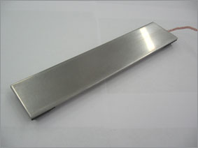
Figure 1
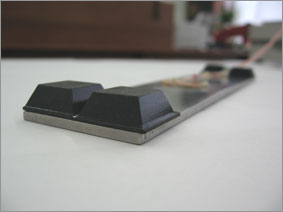
Figure 2
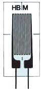
Figure 3
Prior to gluing the resistive strain sensors, the surface of the metal plate has to be cleaned and degreased thoroughly. The measuring (working) resistive strain sensor is attached along the plate, while the compensatory one – in the transverse direction (Figures 4, 5, and 6).
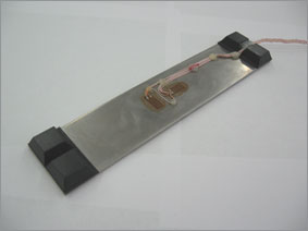
Figure 4
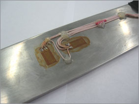
Figure 5
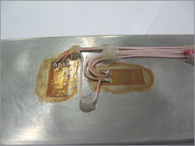
Figure 6
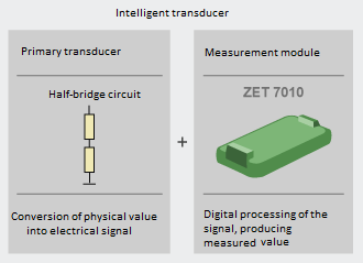
After the glue has dried, the wires shall be soldered to the terminals of the resistive strain sensors according to the diagram shown in Figure 7 (in this case, a half-bridge circuit is used). Rmeas is the measuring resistor glued along the plate. R1 is the compensatory resistor glued across the plate. An MGTF wire with 0.12 mm2 section was used. Then it was braided and fixed on the plate surface with the “POXIPOL” two-part glue (Figure 8).
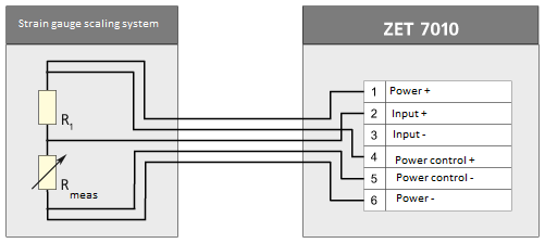
Figure 7
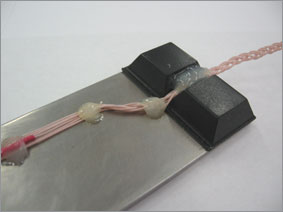
Figure 8
After that, the surface of the resistive strain sensors and soldering points should be coated with a protective varnish (see Figure 6) to protect the resistive strain sensors from mechanical damage. Nitrile-rubber varnish NG150 was used in this case.
After the varnish dries out, you can say “The weigher is ready!”
The only thing left is to connect it to ZET 7010 for measuring. The wires from the weigher are connected in accordance with the connection diagram shown in Figure 7. The circuit power supply will be from the ZET 7010 unit. The measurement results can be displayed on the ZET 7178 digital indicator, or ZET 7010 unit can be connected to a PC using the ZET 7070 interface converter.

Figure 9
The current value of the force applied to the weigher can be displayed on the indicator screen (“DC voltage meter” program). To build a curve of the applied force, the “Multi-channel oscillograph” program is used, and the “Multi-channel self-recorder” program is used for the strain signal parameter monitoring.

Figure 10. Applied load curve
See also:
- Strain gauge measurement
- Strain gauge measurement theory, circuits for resistive strain sensor connection to ZETSENSOR
- Strain gauge measuring bridge circuits generation for measuring various parameters
- Strain gauge bridge types
- Strain gauge use for physical value measuring
- ZET 7010 Tensometer-485 smart RS-485 output strain sensor (static measurements)
- ZET 7110 Tensometer-CAN smart CAN output strain sensor (static measurements)
- ZET 7110 Tensometer-CAN smart CAN output strain sensor for dynamic measurements