Connecting Strain Gauge Sensing Elements
to ZET-017-T8 Strain Gauge Module
This section describes the layouts of resistive strain sensor connection to ZET 017-T8 strain gauge module and issues of measurements using ZETLAB TENZO software supplied with strain gauge modules.
ZET 017-T8 strain gauge module has miniXLR 92M-502 input channels and is supplied with cables for connection of strain gauge sensing elements and resistive strain sensors for each channel.
| Input Channel Connector of Strain Gauge Module | Cable Terminals |
| Input – | IN – |
| Input + | IN + |
| Generator | GEN |
| Ground | GND |
| TEDS Autodetect | — |

Strain Gauge Module inputs
Input- and Input+ contact points form the differential input of the strain gauge module which receives the signal from sensor (strain-gauge bridge).
Generator contact point is designed for supplying the power to sensor from an integrated generator of strain gauge module. The generator is controlled via Signal Generator software, and the signal is forwarded to all strain gauge module channels.
Note: The generator also has a BNC output on the rear panel of strain gauge module.
Measurements are performed via Strain Gauge software. There is a separate software facility for each of the channels. One can use several software facilities for a single measuring channel and adjust them for measurement of various parameters according to the relevant calibration charts. All settings are made in the Options window of Strain Gauge program. Besides the Device manager software application allows to assign signal conversion frequencies and measuring channels names.
The signal at the strain gauge sensor output is proportional to the supplied power and applied load, thus, in order to obtain the measured values it is necessary to perform relative measurements, i.e. take into account the circuit power. For this purpose one can use generator virtual channel or strain gauge module input channel.
The Strain Gauge program displays the current measured value as well as creates a virtual channel available for display on a multi-channel oscillograph, signal parameters recorder, and in other ZETLAB TENZO software facilities.
Layouts of Resistive Strain Sensor Connection to Strain Gauge Module
The figures below show examples of resistive strain sensor connection to strain gauge module via four- and six-wire circuits.
Bridge Circuit
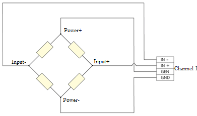
Bridge connection circuit for resistive strain sensors (full bridge). One input channel is used for connection to strain gauge module (four-wire connection circuit). Measurements are relative to the virtual channel of the generator.

Bridge circuit, 4-wire connection to strain gauge module
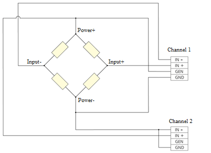
Bridge connection circuit for resistive strain sensors (full bridge). Two input channels are used for connection to strain gauge module: measuring and reference. Measurements are relative to the reference channel.

Bridge circuit, 6-wire connection to strain gauge module
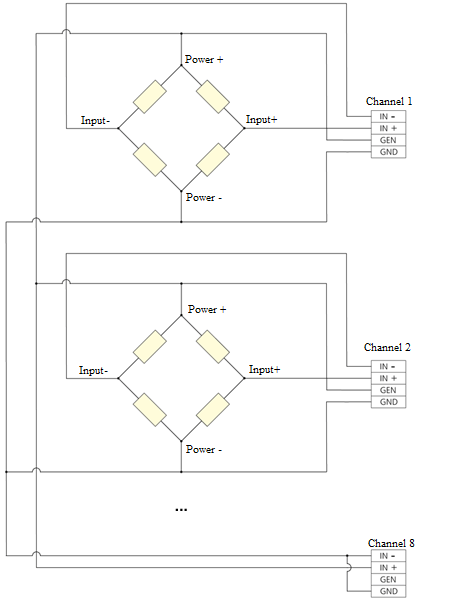
Connection of multiple strain gauge bridges to strain gauge module via one reference channel is used when distances between the measuring points are short.

Connection of multiple strain gauge bridges to strain gauge module via one reference channel
Half-Bridge Circuit
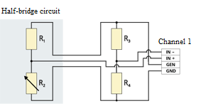
Connection of the half-bridge circuit to the strain gauge module requires resistive strain sensors with low-temperature coefficient of resistance (TCR) for supplementing the circuit to complete the bridge.

R1 — temperature compensation; R2 — measuring; R3, R4 — constants with low TCR; R1≈R2≈R3≈R4
