List of products
compatible with ZETLAB Software

compatible with ZETLAB Software
List of devices compatible with ZETLAB Software.
The technical support is granted free of charge (the drivers and software interfaces are provided for free).
For more information concerning the range of supported functions, application features and channels settings information, please, call us: + 7 (495) 739 39 19 or contact us by E-mail: zetlab@zetlab.com.
| Manufacturer | Device | Protocol |
| STC “Horizont” | Tilt meter IN-D3 | Modbus RTU |
| BD Sensors RUS | Pressure meters DMP 331i | Modbus RTU |
| CJSC “ECOLOGICAL SENSORS AND SYSTEMS” | Thermal anemometer TTM-2-04-02 | Modbus RTU |
| RDC Hydromet | Compact meteorological system MK-26 | Modbus RTU |
| IGM Detector Co ltd | Gas analyzer IGM-10 | Modbus RTU |
| “LIMACO” JSC Russia | Radar level transmitter ULM-11 | Modbus RTU |
New promotional event!
In the course of design and development work, one often needs to test products (especially if the product or its supplier is new).
ZETLAB Company hereby grants you a 60% discount for measuring products samples, so that to simplify the task of selecting new products.
For more details, please, see the Clause «Discounts and promotional events».
via Modbus protocol
In order to connect third-party sensors with Modbus protocol, one should specify the configuration of these sensors in the configuration file of ZETLAB software. For this purpose, we have developed a simple task-oriented Configurator:
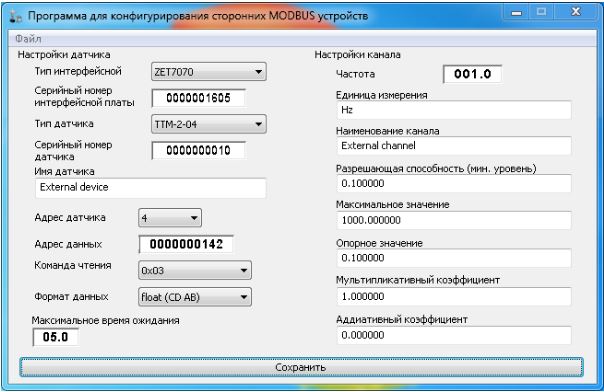
The Configurator program window has a user-friendly dialog interface. Configurator main menu has only a single “File” tab, which, in its turn, has the sub-clauses “Open”, “Create”, “Save”, “Save as”, “Close” and “Exit”.
“Open” key activates a window allowing to select the way to the configuration file to be reconfigured. As the file is selected and the key “Open” is activated, the Configurator will download and display the parameters from the selected configuration file.
Upon activation of the “Create” option, the Configurator will depict the parameters by default.
The “Save” key will make the Configurator to save the new parameters in the recently opened configuration file. If the configuration file has been created as a new one, the “Save” key function will be similar to that of “Save as” key.
Upon activation of the “Save as” key, the Configurator will offer to chose a directory for the newly created or amended configuration file. Click the “Save” key to save the file.
As all the fields are filled and the configuration file is saved, the information of the third-party sensor will be available in the same way, as the information of ZETLAB sensors with Modbus protocol.


Configurator program allows to set the following parameters of the third-party Modbus products:
| Configuration parameter | Description |
| Interface board type | This field specifies the type of Zetlab interface board used (hereinafter referred to as “interface board”) |
| Interface board serial number | This section specifies the interface board serial number |
| Sensor type | This section specifies the third-party Modbus protocol sensor type, which is connected to the interface board (further referred to as the “Sensor”) |
| Sensor serial number | This section specifies the sensor’s serial number |
| Sensor name | This field specifies the name of the sensor used |
| Sensor address | This section depicts the address assigned to the Modbus protocol sensor. |
| Data address | This section specifies the address of the integrated sensor memory, from which the data is to be retrieved via Modbus protocol |
| Read instruction | This field displays the Modbus instruction used for data retrieval from the Sensor |
| Data format | This section specifies the data format used for data storage in the sensor. |
| Max hold time | Stands for the time period upon completion of which the sensor shall be considered to be switched off (currently this option is not available) |
The sensor can have several measured parameters. For instance, the first parameter will be saved to the address 0x0000, the second one – to the 0x0002, the third – to 0x0004, etc. The values of each of the addresses will be further referred to as “channels”.
| Configuration parameter | Description |
| Frequency | This section depicts sampling frequency of the sensor’s channel specified by configuration file (further referred to as the Channel) |
| Measurements unit | This section displays channel’s measurements unit (used for data storage) |
| Channel name | This section shows the name of the active channel |
| Resolution capacity | This section shows the resolution capacity of the current channel |
| Max value | This section shows the maximum modulus value of the active channel |
| Reference value | This section displays reference value of the channel used for further calculations |
| Multiplication ratio | This section shows multiplication ratio of the values conversion for the active channel |
| Additive ratio | This section shows additive ratio of the values conversion for the active channel |