
Theory Of Strain Gauge Measurements, Resistive Strain Sensors Connection Schemes
A Little Bit of Physics
Let us consider a cylindrical conductor (wire), which is stretched at F force. The wire volume v remains constant, while the cross-section is reduced and the length increases. Conductor resistance can be presented as:
![]()
where ρ is resistivity of the material.
After differentiation, we obtain a formula for determining the sensitivity of resistance to wire stretching:
![]()
The sensitivity increases with growing length and resistivity of the wire, and decreases with increasing cross-section of the wire. The relative change of wire resistance against the relative strain can be presented as:
![]()
where Sk is strain gauge sensitivity coefficient. For metal wires it makes 2 to 6, and for semiconductors – 20 to 200.
Let us consider, for instance, the strain gauge resistance with the following characteristics:
| Sensitivity (Sk) | 2.0 |
| Bed material | Polyamide |
| Measuring grid | Constantan foil |
| Base (measuring grid length), mm | 20; 50; 100; 150 |
| Temperature coefficient of sensitivity, 1/K | 115 * 10-6 |
| Transverse sensitivity, % | 0,1 |
| Operating temperature range, °C | -70 to +200 for static measurements -200 to +200 for dynamic measurements |
| Rated resistance, Ohm | 120; 350; 700; 1000 |
Let us consider the strain gauge balance based on the measurement of bending deflection of the beam located on two supports (Figure 1).

Figure 1
Bending deflection is:
![]()
where F is the applied force in the middle of the beam, l is the beam length, I is moment of inertia of the beam cross-section. If the beam cross-section is rectangular with width a and height b, then
![]()
For circular cross-section with radius r:
![]()
Bending radius of the beam will be:
![]()
If a resistive strain sensor is attached to the bottom of the rectangular beam, the relative strain of the sensor will be:
![]()
Let us assume that the steel beam has cross-section a = b = 1 cm = 10-2 m and length l = 10 cm = 10-1 m, then force F = 8,000 N will correspond to bending deflection λ = 1 mm , which corresponds to 800 kg weight. The relative strain of the resistive strain sensor attached to bottom of the beam will be 0.006 with 0.012 relative change of resistance. To establish the balance with definition of 1 kg, we need to record the relative change of resistance up to 10-5.
The following table presents the Young’s modulus and strength limit for some materials.
| Material | Young’s Modulus, 109 N/m2 | Strength Limit, 107 N/m2 |
| Steel | 196 | 127 |
| Iron | 186 | 33 |
| Copper | 120 | 24 |
| Brass | 102 | 35 |
| Aluminum | 68 | 7.8 |
| Lead | 1.7 | 1.5 |
Measuring Circuit
Usually, there are three circuits for connecting resistive sensors. The first circuit (Figure 2) is full-bridge, the second (Figure 3) and third (Figure 4) are half-bridge. The first and second circuits control the supplied voltage and measure the relative voltage drop V1/V2. The third circuit measures V1 voltage relative to the supplied voltage.
As resistances R1-R3, the resistive strain sensor identical to the measuring ones are typically used, but attached to the beam in transverse direction, which is not sensitive to strain. This is primarily due to the high temperature coefficient of resistance of the resistive strain sensor. When using as R1-R3 the same resistive strain sensors under the same conditions as the measuring resistive strain sensor, it becomes much easier to ensure temperature compensation of the bridge circuit. To facilitate that, a six-wire measuring circuit is required. One wire pair powers the bridge, another wire pair measures the supplied voltage, the third wire pair measures the electric potential difference within the bridge circuit.
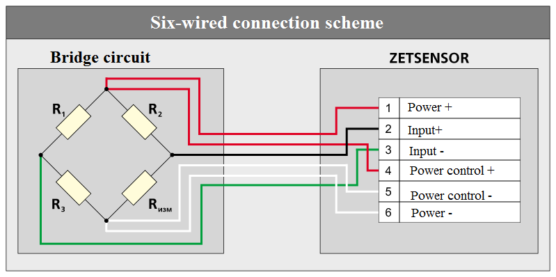
Figure 2
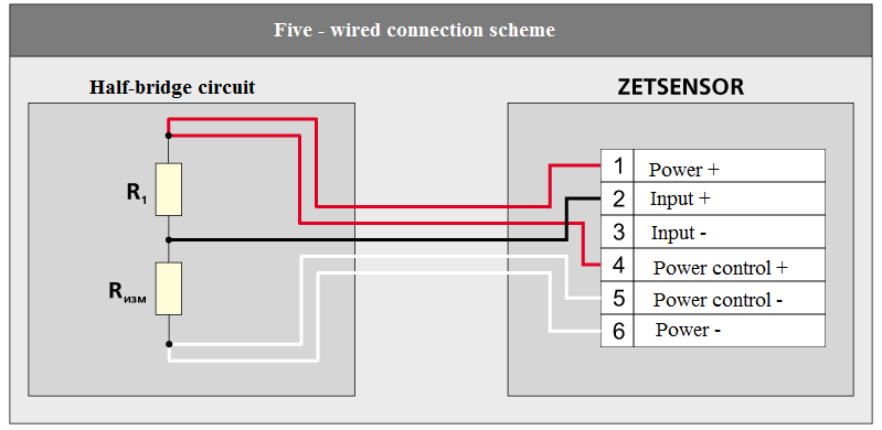
Figure 3
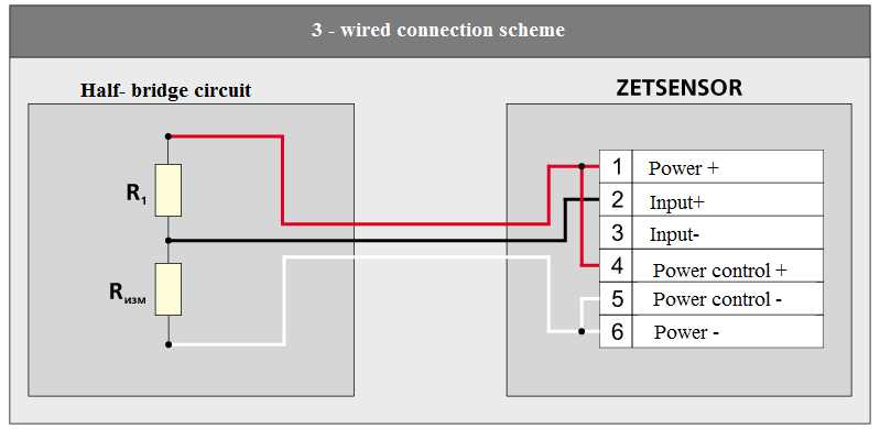
Figure 4
The application of six-wire sensor connection circuit excludes error of voltage drop on leads and the voltage drop changes on leads caused by the temperature dependence of resistance. Another source of error is the noise pickup from from other circuits. The most relevant is the network interference of 50 Hz. The longer the leads, the higher the noise pickup. To reduce the pickup, the twisted-pair screened wires shall be used.
During measurements within the bridge circuit, the output signal is:
![]()
If resistances R1 = R2 = R3 = R, then:
![]()
For half-bridge circuit:
![]()
Another source of interference is non-linear dependence of the voltage drop on the measured value of resistance.
Tensoresistance Sensors
The tensoresistance principle allows to manufacture the pressure sensors with internal bridge circuit.
Photoresistance sensors are sensors, the resistance of which varies depending on the ambient light. In the dark, this sensor demonstrates high resistance, and when lighted, the resistance decreases. This sensor has a non-linear characteristic.
There is also a wide variety of potentiometric sensors – position sensors, rate-of-turn sensors. The principle of measurement of resistance of such sensors is similar to measuring the resistance of temperature-sensitive resistor.
The capacitive and induction sensors have similar function. For example, the induction sensor of linear displacement is based on the half-bridge circuit with 350 Ohm input resistance. A carrier frequency of 5 kHz is required for powering the sensor. The sensor consists of two transformer windings. One transformer winding is supplied with AC voltage, the other winding delivers the output signal. Retractable probe is made of ferromagnetic material. Depending on the position of the probe, the transformation coefficient between windings changes along with the corresponding change of the output signal amplitude. The output signal amplitude determines the probe displacement. The linearity of such sensor does not exceed 1-2%.
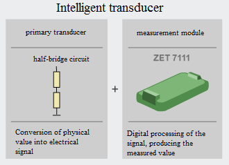
ZETLAB offers ZETSENSOR series measuring modules for each sensor type. Specifically designed to address a particular measuring task, ZETSENSOR modules allow to connect primary transducers directly, i.e. bypassing the matching, amplifying circuits and power circuits. The power is supplied from measuring module in form of AC (static measurements) or DC (dynamic measurements). The sensor signals are processed directly by the measuring module, and the measurement results are transmitted in digital form via RS-485 or CAN interface using the Modbus protocol. The measurement results can be displayed on a digital indicator or PC. ZETSENSOR control modules implement the control and management systems, both on PC and offline.
 |
 |