Measurements of the unbalances
During the design of machines and mechanisms, developers look forward to achieve the weighting symmetry of all the moving parts in order to eliminate the occurrence of harmful vibrations. However, in practice, it is rarely possible to design a perfectly balanced detail, moreover, during operation the run-out of the detail occurs and as a result its unbalance. Balancing of the bodies of rotation is carried out by changing their weight or configuration. This process is called balancing adjustment.
The system of determination of the unbalance parameters is designed to carry out measurements required while balancing such units as pulleys, gear wheels, electric motor rotors, flywheels, drums, crankshafts, etc. The main functional units of the system are the speed sensor, the acceleration indicator, and the spectrum analyzer.
Mounting of the sensors
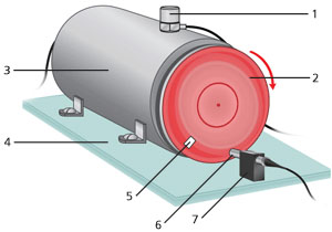
The location of the sensors plays a significant role in measuring the unbalance (disbalance) parameters. The relative location of the speed sensor and acceleration indicator is taken into account in determining the direction of the unbalance; therefore, it is required to fix securely the acceleration indicator, the stationary body of the balanced element and the speed sensor together. It is desirable to use the common platform and the speed sensor mounting for that purpose. The common platform is to be placed horizontally, while the plane of the rotating disk of the balanced element is to be vertical (see the figure below).
1 – acceleration indicator,
2 – rotating disk of the balanced element,
3 – stationary body of the balanced element,
4 – common platform,
5 – light-reflecting label,
6 – speed sensor,
7 – speed sensor hold; the red handle shows the rotation direction of the disc (clockwise)
Mounting of the acceleration indicator
The optimized surface for the acceleration indicator mounting is the highest point of the balancing plane on the stationary body of the balanced element. It is recommended to provide the fixation of the acceleration indicator in accordance with the requirements ISO 5348:1998 “Mechanical vibration and shock. Mechanical mounting of accelerometers”. It is possible to mount the acceleration indicator with a stud with a thread M5 or with a thin layer of glue. If the body can not be subjected to drilling and the use of glue is also not possible, and the body is made of a magnetic material, the acceleration indicators are to be mounted onto the body by magnetic fasteners АМ50. Otherwise, the acceleration indicators are to be mounted to the body with paste, made on the basis of beeswax, for example, the paste AW01.
The surface on which the acceleration indicator is mounted is to be smooth and clean. The discrepancy between the acceleration indicator axis and the vertical should be minimized. When using magnetic fasteners it is not recommended to mount the acceleration indicator on the top of the body because herein the acceleration indicator is mounted with a shock, accompanied by a well audible click, which can lead to the acceleration indicator transducing element failure. In this case, it is recommended to mount the acceleration indicator, making a horizontal motion, as if pushing it from a side on the place of mounting.
Mounting of the speed sensor
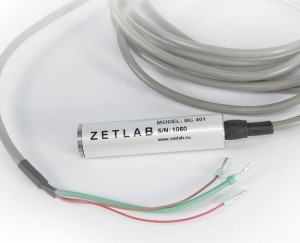
The speed sensor is mounted in such a way that the end plane with light elements of the sensor (see the figure below) was parallel to the plane of the disc with a light-reflective label, and the line passing through the light elements was vertical. The distance between the light elements of the sensor and the rotating disk should be at least 2 mm but no more than 15 mm.
The light-reflective label is mounted on the external rotating disc of the balanced element. The layout chart of the label on the disc is shown in the figure below. The reflection factor of the label in the operating frequency range of the speed sensor in use is to be different at least on an order of the reflective factor of the disk itself. Thus, the label for the black disk is to be made of the self-adhesive white paper. The paper for the label is to be black for the bright disk.
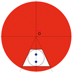
The Schematic representation of the disc of the balanced element (red) with light-reflective label (white). The point “О” is the center of the disc. On the label: the dotted circle is the projection of the end face plane of the speed sensor to the label; two blue dots are the light elements of the sensor. Side border of the label coincide with the radii of the disc
The radius of the label location r is connected to the maximum frequency of balancing fbal (r/min) and the sampling frequency of the signal digitalization fadc (Hz).
Let’s introduce the notion Тadc=1/fadc (sec).
The time during which the label makes a complete rotation Тbal=60/fbal (sec). The center of the label passes the way 2πr at this time.
The time of the movement of the label with width L past the speed sensor ВС 401:
t=ТbalL/(2πr)=60L/(2πr·fbal)=30L/(πr·fbal)
In order to carry out the measurement it is necessary that t≥3Тadc:
30L/(πr·fbal)≥3/fadc ⇒ r·fbal≤fadc10L/π
Thus, for a label with width L=1,25* cm with the sampling frequency of the signal digitalization fadc=25,000 Hz and the frequency of balancing fbal=32,000 r/min, the radius of the location of the center of the label is to be r≤3.125 cm.
*optimized width of the label is width L, which is equal to the diameter of the speed sensor in use.
Processing the signals from the sensors
The presence of the unbalance can be charged by the amplitude of the displacement signal, obtained by double integration and subsequent filtering of the signal of the acceleration indicator. The direction of the unbalance is determined by the displacement signals and signals of the speed sensor.
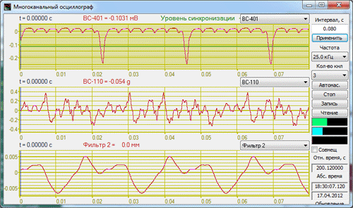
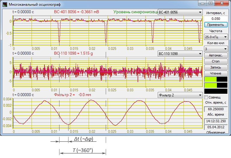
Let’s look at the example presented on the figure below. The waveforms of the three signals are visualized on the screen of the program “Multi-channel oscilloscope”:
- the signal of the speed sensor ВС 401;
- acceleration signal – the initial signal of the acceleration indicator ВС 110;
- displacement signal – the processed signal from the acceleration indicator Filter 2.
The Waveform of the signal of the speed sensor (upper graph) is a periodic signal with pulses, representing the sensor reaction to the movement of light-reflective label around the light elements of the sensor. There are negative narrow pulses in the Figure. The values of the signal in absence of the label near the speed sensor can be arbitrarily changed depending on the reflectivity of the disc portions that move around speed sensor. If the disc contains some heterogeneity, it can lead to significant fluctuations of the speed sensor signal. This can lead to mistakes in the frequency measurement in the automatic mode, thus such fluctuations must not exceed 1/2 of the amplitude of the signal speed sensor. According to the signal of the speed sensor, the T signal period is determined (the distance between the peaks).
The waveform of the signal of the acceleration indicator (middle graph) at large values of the imbalance will be represent a periodic signal, the period of which shall be equal to the period of the signal of the speed sensor. The periodicity in the signal of the acceleration indicator may not be observed at small values of unbalance. The initial signal of the acceleration indicator is not directly used to analyze unbalance parameters.
The waveform of the displacement signal (lover graph) reflects the state of the product. The signal strength is proportional to the unbalance value. If there is a localized unbalance presented in a periodic signal, the period of which is equal to the period of the signal of the speed sensor, and the offset of the signal of the speed sensor is proportional to the angle of unbalance. The presence of several localized unbalances in the tested unit is reflected by several extremes in the displacement signal, as shown above.
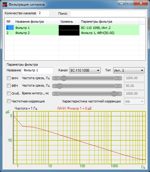
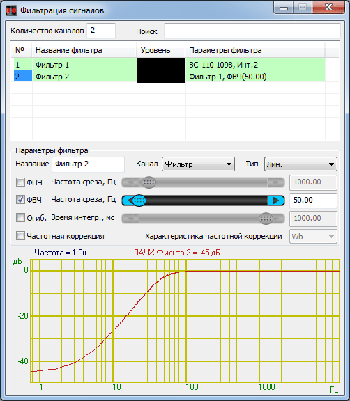
The processing of the signal of the acceleration indicator is carried out by the program “Filtration of the signals” with usage of double integration functions to receive the displacement signal and the HPF filter. The cutoff frequency is selected in such a way that the filter “transmitted” the useful signal (i.e. below the signal frequency); herein it is necessary to achieve the stability of the filtered signal (i.e. absence of the signal displacement relatively to 0).
Determination of unbalance parameters
Determination of unbalance parameters
The physical meaning of the unbalance amount d is expressed by the formula:
d=m·r
i.e., the product of the unbalanced mass m at a distance r from the rotation axis.
In practice, the imbalance leads to the presence of vibration during rotation of the shaft, resulting in an accelerometer mounted on the product affects the acceleration. The vibration displacement signal is obtained by double integration of the acceleration signal at the point at which the accelerometer is attached. The amplitude of vibration displacement signal is directly proportional to the imbalance, and the proportionality factor kf depends on the weight and size products and speed. Thus, the magnitude of imbalance may be defined by the formula:
d=kf·A
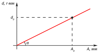
kf factor is easily determined experimentally, by measuring the amplitude of vibration displacement signal A0 for a known value of imbalance. To do this, you must install the load balanced rotor mass m0 at a distance r0 and by calculating the value of d0 imbalances build directly from the origin through the point (d0, A0).
The slope of the resulting straight line is a factor depending on the value of the imbalance of the signal amplitude of vibration displacement:
kf=tg(α)=d0/A0.
In further calculations, this value can be used for rotors of the same type (with the same weight and size) when tested at the same frequency f.
Determining the direction of the imbalance
In order to determine the direction of the imbalance it is necessary to determine the value of T signal period (corresponding to one revolution, i.e., 360 °) and extremum value of vibration displacement signal relative to the reference period Δt, (corresponding to the angle of imbalance).
Note: If we consider the location of sensors such as provided in the example, the direction of imbalance in this case is determined by the negative peak.
Unbalance angle is determined according to the formula:
Δφ = (Δt/T)·360°
The angle of the imbalance (the average unbalance) is measured from the center of the retro-reflective label in the opposite side of the balanced rotation of the product (at a specified location of sensors).
Remarks:
1) If the Δt value while changing the test product, i.e. displacement signal “drifts” relative to speed sensor signal, this means that the unbalance is not clear localization and balancing product is prevented;
2) If the motion sensor signal is more negative (and therefore positive) peaks, it indicates the presence of several localized imbalances.
Measurements using oscilloscope with subsequent calculation of the imbalance parameters are quite suitable for single measurements, for example, in the study of the theory of balancing. However, during the balancing products on an industrial scale measurements must be carried out quickly and with minimal operator involvement.
Rotor balancing system was created by our developers to automate measurements.

